Aim: To determine the values of constant k and n.
Apparatus/Materials: Steel balls, engine oil, stopwatch, meter rule, magnet, glass tube, rubber
bung
Diagrams:
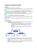
Diagram showing apparatus setup of the glass tube attached to the clamp stand.
Procedure:
1. A clamp and retort stand was assembled and placed on a table as shown in the diagram.
2. A glass tube was fitted firmly to the stand.
3. A rubber bung was fastened to the bottom of the glass tube.
4. The tube was filled with transparent engine oil A. Then, the oil was allowed to equilibrate for
some time to ensure that no air bubbles were present.
5. The diameter of the spheres were measured twice and the radius was calculated.
6. The time taken for the spheres to fall from X to Y was measured. The time measurements
were done twice for each oil.
7. All measurements and calculations were recorded in a suitable table.
8. The equation v=krⁿ was used to determine the constants k and n where v was the terminal
velocity and r was the radius of the spheres.
, Variables:
Manipulated Variable:
1. The brand of engine oils used.
Controlled Variables:
1. The mass of the ball.
2. The distance the ball travelled.
Responding Variable:
1. The time taken for the ball to fall.
Results:
TABLE 1.1 showing the results taken for engine oil.
Diameter Radius Time t/s Velocity lg lg
d/mm r/mm 1st 2nd Avg. v/cms-1 (v/cms- (r/mm)
1)
11.75 5.88 2.17 2.11 2.14 42.1 1.6 0.77
8.40 4.20 2.66 2.60 2.63 34.2 1.5 0.62
6.85 3.43 3.19 3.16 3.18 28.3 1.5 0.54
5.52 2.76 4.56 4.58 4.57 19.7 1.3 0.44
4.47 2.24 6.00 6.06 6.03 14.9 1.2 0.35
Apparatus/Materials: Steel balls, engine oil, stopwatch, meter rule, magnet, glass tube, rubber
bung
Diagrams:
Diagram showing apparatus setup of the glass tube attached to the clamp stand.
Procedure:
1. A clamp and retort stand was assembled and placed on a table as shown in the diagram.
2. A glass tube was fitted firmly to the stand.
3. A rubber bung was fastened to the bottom of the glass tube.
4. The tube was filled with transparent engine oil A. Then, the oil was allowed to equilibrate for
some time to ensure that no air bubbles were present.
5. The diameter of the spheres were measured twice and the radius was calculated.
6. The time taken for the spheres to fall from X to Y was measured. The time measurements
were done twice for each oil.
7. All measurements and calculations were recorded in a suitable table.
8. The equation v=krⁿ was used to determine the constants k and n where v was the terminal
velocity and r was the radius of the spheres.
, Variables:
Manipulated Variable:
1. The brand of engine oils used.
Controlled Variables:
1. The mass of the ball.
2. The distance the ball travelled.
Responding Variable:
1. The time taken for the ball to fall.
Results:
TABLE 1.1 showing the results taken for engine oil.
Diameter Radius Time t/s Velocity lg lg
d/mm r/mm 1st 2nd Avg. v/cms-1 (v/cms- (r/mm)
1)
11.75 5.88 2.17 2.11 2.14 42.1 1.6 0.77
8.40 4.20 2.66 2.60 2.63 34.2 1.5 0.62
6.85 3.43 3.19 3.16 3.18 28.3 1.5 0.54
5.52 2.76 4.56 4.58 4.57 19.7 1.3 0.44
4.47 2.24 6.00 6.06 6.03 14.9 1.2 0.35