Norman S. Nise
CONTROL SYSTEMS
E N GIN EERIN G
Seventh Edition
10/21/14 1
,
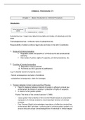
,Antenna Azimuth Position
Control System
Layout
Potentiometer
Antenna
θi(t)
θo(t)
Desired Azimuth
azimuth angle angle
input output
Differential amplifier
and power amplifier
Motor Potentiometer
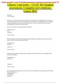
Schematic
θi (t) +V
n-turn potentiometer
Fixed
Differential Power Motor field
–V
preamplifier amplifier Ra
vi (t) + vp (t) ea (t)
K1 θm(t)
vo (t) – K s+a
Ja kg-m2 N1
Da N-m s/rad Gear θo (t)
Kb V-s/rad
Armature
Kt N-m/A N2
JL kg-m2
–V Gear
DL N-m-s/rad
N3
n-turn potentiometer
Gear
+V
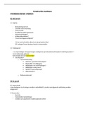
, Block Diagram
Desired Power Motor
azimuth Azimuth
Potentiometer Preamplifier amplifier and load Gears angle
angle
θi (s) Vi (s) + Ve (s) Vp (s) K1 Ea(s) K1 θ m(s) θo (s)
Kpot K Kg
s+a s(s+am)
–
Potentiometer
Kpot
Schematic Parameters
Parameter Configuration 1 Configuration 2 Configuration 3
V 10 10 10
n 10 1 1
K — — —
K1 100 150 100
a 100 150 100
Ra 8 5 5
Ja 0.02 0.05 0.05
Da 0.01 0.01 0.01
Kb 0.5 1 1
Kt 0.5 1 1
N1 25 50 50
N2 250 250 250
N3 250 250 250
JL 1 5 5
DL 1 3 3
Block Diagram Parameters
Parameter Configuration 1 Configuration 2 Configuration 3
Kpot 0.318
K —
K1 100
a 100
Km 2.083
am 1.71
Kg 0.1
Note: reader may fill in Configuration 2 and Configuration 3 columns after completing
the antenna control Case Study challenge problems in Chapters 2 and 10, respectively.
CONTROL SYSTEMS
E N GIN EERIN G
Seventh Edition
10/21/14 1
,
,Antenna Azimuth Position
Control System
Layout
Potentiometer
Antenna
θi(t)
θo(t)
Desired Azimuth
azimuth angle angle
input output
Differential amplifier
and power amplifier
Motor Potentiometer
Schematic
θi (t) +V
n-turn potentiometer
Fixed
Differential Power Motor field
–V
preamplifier amplifier Ra
vi (t) + vp (t) ea (t)
K1 θm(t)
vo (t) – K s+a
Ja kg-m2 N1
Da N-m s/rad Gear θo (t)
Kb V-s/rad
Armature
Kt N-m/A N2
JL kg-m2
–V Gear
DL N-m-s/rad
N3
n-turn potentiometer
Gear
+V
, Block Diagram
Desired Power Motor
azimuth Azimuth
Potentiometer Preamplifier amplifier and load Gears angle
angle
θi (s) Vi (s) + Ve (s) Vp (s) K1 Ea(s) K1 θ m(s) θo (s)
Kpot K Kg
s+a s(s+am)
–
Potentiometer
Kpot
Schematic Parameters
Parameter Configuration 1 Configuration 2 Configuration 3
V 10 10 10
n 10 1 1
K — — —
K1 100 150 100
a 100 150 100
Ra 8 5 5
Ja 0.02 0.05 0.05
Da 0.01 0.01 0.01
Kb 0.5 1 1
Kt 0.5 1 1
N1 25 50 50
N2 250 250 250
N3 250 250 250
JL 1 5 5
DL 1 3 3
Block Diagram Parameters
Parameter Configuration 1 Configuration 2 Configuration 3
Kpot 0.318
K —
K1 100
a 100
Km 2.083
am 1.71
Kg 0.1
Note: reader may fill in Configuration 2 and Configuration 3 columns after completing
the antenna control Case Study challenge problems in Chapters 2 and 10, respectively.