6) use of VOR / ADF RMI
1. The Radio Magnetic Indicator
(RMI)
2. Homing to an NDB/VOR Beacon
3. Tracking to an NDB/VOR
4. Tracking from an NDB/VOR
5. Interceptions
6. Procedure Turns
7. Holding Patterns
Briefings IRI 06 use of VOR / ADF RMI rev 2 : 05 2021 Page 1
, 1. The Radio Magnetic Indicator (RMI)
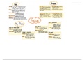
The RMI is used both for ADF and VOR bearing
information.
The ADF needle on the RMI is still effectively
showing the relative bearing of the NDB (the NDB
bears 005° relative to the aircraft nose, and the
sharp end of the needle is 005° removed from the
top of the RMI). The difference is that the compass
rose on the RMI is slaved to the aircraft
gyrocompass and presently indicates the aircraft
heading of 360° (M) at the top of the instrument.
The RMI has therefore mechanically added the
magnetic heading to the relative bearing and the
needle shows the magnetic bearing of the NDB from
the aircraft.
The VOR bearing is displayed on the RMI with the
sharp end of the needle pointing to the VOR station.
QDR 275 / QDM 095
It is probable that the compass to which the RMI is slaved will suffer small amounts of deviation.
• The amount of any deviation should be very small (certainly less than one degree for a
sophisticated gyro-slaved system) and is normally ignored.
• Should the amount of deviation become significant it is necessary to correct ADF bearings
on the RMI; VOR bearings are NOT affected because the equipment first subtracts aircraft
heading to produce a relative bearing which controls the pointer, but on the display aircraft
heading is re-applied to give the ORIGINAL QDM as the output.
Briefings IRI 06 use of VOR / ADF RMI rev 2 : 05 2021 Page 2
1. The Radio Magnetic Indicator
(RMI)
2. Homing to an NDB/VOR Beacon
3. Tracking to an NDB/VOR
4. Tracking from an NDB/VOR
5. Interceptions
6. Procedure Turns
7. Holding Patterns
Briefings IRI 06 use of VOR / ADF RMI rev 2 : 05 2021 Page 1
, 1. The Radio Magnetic Indicator (RMI)
The RMI is used both for ADF and VOR bearing
information.
The ADF needle on the RMI is still effectively
showing the relative bearing of the NDB (the NDB
bears 005° relative to the aircraft nose, and the
sharp end of the needle is 005° removed from the
top of the RMI). The difference is that the compass
rose on the RMI is slaved to the aircraft
gyrocompass and presently indicates the aircraft
heading of 360° (M) at the top of the instrument.
The RMI has therefore mechanically added the
magnetic heading to the relative bearing and the
needle shows the magnetic bearing of the NDB from
the aircraft.
The VOR bearing is displayed on the RMI with the
sharp end of the needle pointing to the VOR station.
QDR 275 / QDM 095
It is probable that the compass to which the RMI is slaved will suffer small amounts of deviation.
• The amount of any deviation should be very small (certainly less than one degree for a
sophisticated gyro-slaved system) and is normally ignored.
• Should the amount of deviation become significant it is necessary to correct ADF bearings
on the RMI; VOR bearings are NOT affected because the equipment first subtracts aircraft
heading to produce a relative bearing which controls the pointer, but on the display aircraft
heading is re-applied to give the ORIGINAL QDM as the output.
Briefings IRI 06 use of VOR / ADF RMI rev 2 : 05 2021 Page 2