COMPUTER 2210 HANOUTS
GCE OLEVELS
3 Logic gates and logic circuits
3.1 Logic Gates
Electronic circuits in computers, many new memories and controlling devices are made
up of thousands of LOGIC GATES. Logic gates take binary inputs and produce a binary output.
Several logic gates combined together form a LOGIC CIRCUIT and these circuits are designed
to carry out a specific function.
3.2 Truth Tables
Truth tables are used to trace the output from a logic gate or logic circuit. The NOT gate
is the only logic gate with one input; the other five gates have two inputs.
When constructing truth tables, all possible combinations of 1s and 0s which can be
input are considered. For the NOT gate (one input) there are only 21 (2) possible binary
combinations. For all other gates (two inputs), there are 22 (4) possible binary combinations.
Number of possible binary combinations can be obtained by using the formula 2n (Where
n is the number of inputs)
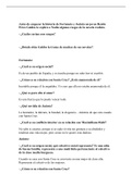
3.2.1 Truth Table for 2 Inputs
For all logic gates (except NOT gate) there are two inputs. Using the formula above,
there are 22 (4) possible binary combinations.
Figure 1 Truth Table-2 Inputs
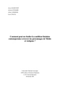
3.2.2 Truth Table for 3 Inputs
For logic circuits, the number of inputs can be more than 2; for example three inputs give
a possible 23 (8) binary combinations.
Figure 2 Truth Table - 3 Inputs
3.3 Functions of Logic Gates
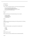
3.3.1 NOT Gate
It is a unary gate, which means it can operate on a single input at a time.
Figure 3: NOT gate
,a) Description:
The output, X, is 1 if the input, A, is 0
The output, X, is 0 if the input, A, is 1
b) How to write this:
X = NOT A (logic notation)
X = ā (Boolean algebra)
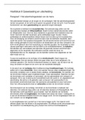
c) Truth Table of NOT Gate
Figure 4 Truth Table-NOT Gate
3.3.2 AND Gate
It is a binary operator used for logical multiplication. Output of AND gate is one if and only if both
Inputs are 1, otherwise output will be 0.
Figure 5 AND Gate
a) Description:
The output, X, is 1 if both inputs, A and B, are 1
b) How to write this:
X = A AND B (logic notation)
X = a · b (Boolean algebra)
c) Truth table of AND Gate
Figure 6 Truth Table AND Gate
3.3.3 OR Gate
It is a binary gate used for logical addition. Output of OR operation will be 1 if any of the input is
1
Figure 7 OR Gate
, a) Description:
The output, X, is 1 if either input, A or B, is 1
b) How to write this:
X = A OR B (logic notation)
X = a + b (Boolean algebra)
c) Truth table of OR Gate
Figure 8 Truth Table- OR Gate
3.3.4 NAND Gate (Not of AND)
a) Description
The output (X) is true (i.e. 1 or ON) if: any of the input is 0
b) How to write this:
X = A NAND B (logic notation)
c) Truth table of NAND Gate
3.3.5 NOR Gate (Not of OR)
a) Description
The output (X) is true (i.e. 1 or ON) if: all of the inputs are 0
b) How to write this:
X = A NOR B (logic notation)
GCE OLEVELS
3 Logic gates and logic circuits
3.1 Logic Gates
Electronic circuits in computers, many new memories and controlling devices are made
up of thousands of LOGIC GATES. Logic gates take binary inputs and produce a binary output.
Several logic gates combined together form a LOGIC CIRCUIT and these circuits are designed
to carry out a specific function.
3.2 Truth Tables
Truth tables are used to trace the output from a logic gate or logic circuit. The NOT gate
is the only logic gate with one input; the other five gates have two inputs.
When constructing truth tables, all possible combinations of 1s and 0s which can be
input are considered. For the NOT gate (one input) there are only 21 (2) possible binary
combinations. For all other gates (two inputs), there are 22 (4) possible binary combinations.
Number of possible binary combinations can be obtained by using the formula 2n (Where
n is the number of inputs)
3.2.1 Truth Table for 2 Inputs
For all logic gates (except NOT gate) there are two inputs. Using the formula above,
there are 22 (4) possible binary combinations.
Figure 1 Truth Table-2 Inputs
3.2.2 Truth Table for 3 Inputs
For logic circuits, the number of inputs can be more than 2; for example three inputs give
a possible 23 (8) binary combinations.
Figure 2 Truth Table - 3 Inputs
3.3 Functions of Logic Gates
3.3.1 NOT Gate
It is a unary gate, which means it can operate on a single input at a time.
Figure 3: NOT gate
,a) Description:
The output, X, is 1 if the input, A, is 0
The output, X, is 0 if the input, A, is 1
b) How to write this:
X = NOT A (logic notation)
X = ā (Boolean algebra)
c) Truth Table of NOT Gate
Figure 4 Truth Table-NOT Gate
3.3.2 AND Gate
It is a binary operator used for logical multiplication. Output of AND gate is one if and only if both
Inputs are 1, otherwise output will be 0.
Figure 5 AND Gate
a) Description:
The output, X, is 1 if both inputs, A and B, are 1
b) How to write this:
X = A AND B (logic notation)
X = a · b (Boolean algebra)
c) Truth table of AND Gate
Figure 6 Truth Table AND Gate
3.3.3 OR Gate
It is a binary gate used for logical addition. Output of OR operation will be 1 if any of the input is
1
Figure 7 OR Gate
, a) Description:
The output, X, is 1 if either input, A or B, is 1
b) How to write this:
X = A OR B (logic notation)
X = a + b (Boolean algebra)
c) Truth table of OR Gate
Figure 8 Truth Table- OR Gate
3.3.4 NAND Gate (Not of AND)
a) Description
The output (X) is true (i.e. 1 or ON) if: any of the input is 0
b) How to write this:
X = A NAND B (logic notation)
c) Truth table of NAND Gate
3.3.5 NOR Gate (Not of OR)
a) Description
The output (X) is true (i.e. 1 or ON) if: all of the inputs are 0
b) How to write this:
X = A NOR B (logic notation)