Nozzles
All notes, definition, equations, etc., are referenced to Applied Thermodynamics for Engineering
Technologists, 5th Edition, T.D. Eastop and A. McConkey, Chapter 12, Pages 381-416, Pearson
Prentice Hall, 1993
Nozzle Shape
A nozzle is a duct of smoothly varying cross section in which a steadily flowing fluid can be made to
accelerate (increase of stream velocity) by a pressure drop along the duct. Nozzles are used in steam
and gas turbines, jet engines, rocket motors, flow measurement, etc. When a fluid is decelerated in a
duct it is called a diffuser. Diffusers are used in centrifugal compressors.
For fluid acceleration, the convergent and convergent-divergent ducts will be evaluated. In the
evaluation, it will be assumed that the fluid velocity and properties will only change in the direction of
the flow.
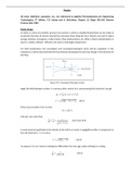
Throat
1
X
p, h1, C1
p, h, C Flow Direction
1 X Outlet
Figure 10.3: Convergent-divergent nozzle
Apply the SFEE between section 1-1 and any other section X-X, and assuming W=0 and Q=0, we get
ℎ + 𝐶 ⁄2 = ℎ + 𝐶 ⁄2
𝐶= 2(ℎ − ℎ) + 𝐶 (10.1)
If the area at section X-X is A, then
𝑚̇ = 𝐶𝐴⁄𝜈
Area per unit mass flow,
̇
= = (10.2 and 10.3)
( )
In most practical applications the velocity at the inlet to a nozzle is negligibly smaller in comparison to
the exit velocity (C1 <<<<C), thus
𝐶= 2(ℎ − ℎ) (10.4)
To express C in m/s, have to multiply by 1000 within the root sign, when enthalpy is in kJ/kg.
̇
= (10.5)
( )
All notes, definition, equations, etc., are referenced to Applied Thermodynamics for Engineering
Technologists, 5th Edition, T.D. Eastop and A. McConkey, Chapter 12, Pages 381-416, Pearson
Prentice Hall, 1993
Nozzle Shape
A nozzle is a duct of smoothly varying cross section in which a steadily flowing fluid can be made to
accelerate (increase of stream velocity) by a pressure drop along the duct. Nozzles are used in steam
and gas turbines, jet engines, rocket motors, flow measurement, etc. When a fluid is decelerated in a
duct it is called a diffuser. Diffusers are used in centrifugal compressors.
For fluid acceleration, the convergent and convergent-divergent ducts will be evaluated. In the
evaluation, it will be assumed that the fluid velocity and properties will only change in the direction of
the flow.
Throat
1
X
p, h1, C1
p, h, C Flow Direction
1 X Outlet
Figure 10.3: Convergent-divergent nozzle
Apply the SFEE between section 1-1 and any other section X-X, and assuming W=0 and Q=0, we get
ℎ + 𝐶 ⁄2 = ℎ + 𝐶 ⁄2
𝐶= 2(ℎ − ℎ) + 𝐶 (10.1)
If the area at section X-X is A, then
𝑚̇ = 𝐶𝐴⁄𝜈
Area per unit mass flow,
̇
= = (10.2 and 10.3)
( )
In most practical applications the velocity at the inlet to a nozzle is negligibly smaller in comparison to
the exit velocity (C1 <<<<C), thus
𝐶= 2(ℎ − ℎ) (10.4)
To express C in m/s, have to multiply by 1000 within the root sign, when enthalpy is in kJ/kg.
̇
= (10.5)
( )

