EEE 334 Lab 2 Online: Experiment| Operational
Amplifiers |2026 Latest Update with Complete
Solution-ASU
EEE 334 Online
Experiment {2}
{Operational Amplifiers}
Introduction:
- What is this experiment about?
This Experiment is to study and observe the properties of amplifiers whether they are
connected in the inverting or non-inverting settings. Also, the to study the use of op-amps
like integration or differentiating amplifiers.
- What components or special equipment will be used?
Op-amps, resistors, wires, breadboard, Analog discovery unit, and a multimeter.
Also, Waveform and LTspice programs
1
,Equipment and Components:
a. Equipment
Name Model Quantity
ADK Unit 2 1
ADK kit 1
Waveform application 1
LTspice application 1
b. Components
Name Value Quantity
Resistors 10KOhms, 1KOhms 1 each
Op-ams Op27 1
Capacitor .01uF 1
Course of Action:
Be sure to include:
- Number and name of experiment section
- Circuit schematics with named figure labels
- Logical steps of the course of action to obtain all results (include calculations)
2
, Course of Action:
2.1
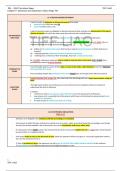
1. Calculate the voltage gain of the circuit in fig 2.1.
Using Av = -Rf/Rs, Av = -10 V
2. Stimulate the circuit in LTspice. Do transient analysis as well as AC sweep to obtain the
frequency response.
3. We need to locate f3dB using 20log10 (|Vout/Vs|), also we need to find ft which the
frequency at 0db gain.
4. We need to build our circuit. Our output will be 0.4v, two power supplies (5V, -5V), Vpp
0.2 Amplitude, Rf = 10Kohms, Rs = 1Kohms, and sine wave at 1kHz. Keeping in mind to
turn on the DC signal (-5V) before turning on the AC signal (5V).
5. Finally we have to observe both the input and the output waveforms and we need to
verify that they are out of phase and take a screen shot to attached in the lab report. Also
measure the input and output voltage using the ADK multimeter and we have to determine
the amplifier gain.
2.2
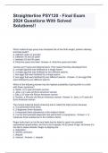
1. First, we have to find the gain which using the formula it
should be
Av = Rf/Rs = 10KOhms / 1KOhms = 10 V
2. We have to stimulate the circuit with LTspice using the same op-amp, voltage input,
and resistors to plot both the input and the output voltages. Also, we need an AC
sweep to determine the frequency response for the transfer function.
3. After that we have to locate f3db and ft (unity gain)
4. We build the circuit on a breadboard using the same resistors and input and output
voltages like we did in 2.1.
5. We have to observe the waveform on the ADK oscilloscope and verify that both the
input and output are in phase.
6. We have to screenshot the waveform and include the screenshot here in the result
section.
7. Finally, we have to measure the RMS Input and output voltages using our
multimeter, and we have to determine the amplifier gain.
2.3
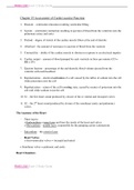
1. We start by calculating the gain in the circuit shown in fig. 2.4.
2. After that we have to stimulate the circuit in LTspice using a
square wave input instead of a sine wave. We have to use .02V
amplitude at 1KHz, .01uF capacitor and Rs = 10Kohms
3. We need to do a transient analysis to view Vout and Vs
determine their relationship. We need to observe different
times to see the cycle settle. Also, we have to determine
3
Amplifiers |2026 Latest Update with Complete
Solution-ASU
EEE 334 Online
Experiment {2}
{Operational Amplifiers}
Introduction:
- What is this experiment about?
This Experiment is to study and observe the properties of amplifiers whether they are
connected in the inverting or non-inverting settings. Also, the to study the use of op-amps
like integration or differentiating amplifiers.
- What components or special equipment will be used?
Op-amps, resistors, wires, breadboard, Analog discovery unit, and a multimeter.
Also, Waveform and LTspice programs
1
,Equipment and Components:
a. Equipment
Name Model Quantity
ADK Unit 2 1
ADK kit 1
Waveform application 1
LTspice application 1
b. Components
Name Value Quantity
Resistors 10KOhms, 1KOhms 1 each
Op-ams Op27 1
Capacitor .01uF 1
Course of Action:
Be sure to include:
- Number and name of experiment section
- Circuit schematics with named figure labels
- Logical steps of the course of action to obtain all results (include calculations)
2
, Course of Action:
2.1
1. Calculate the voltage gain of the circuit in fig 2.1.
Using Av = -Rf/Rs, Av = -10 V
2. Stimulate the circuit in LTspice. Do transient analysis as well as AC sweep to obtain the
frequency response.
3. We need to locate f3dB using 20log10 (|Vout/Vs|), also we need to find ft which the
frequency at 0db gain.
4. We need to build our circuit. Our output will be 0.4v, two power supplies (5V, -5V), Vpp
0.2 Amplitude, Rf = 10Kohms, Rs = 1Kohms, and sine wave at 1kHz. Keeping in mind to
turn on the DC signal (-5V) before turning on the AC signal (5V).
5. Finally we have to observe both the input and the output waveforms and we need to
verify that they are out of phase and take a screen shot to attached in the lab report. Also
measure the input and output voltage using the ADK multimeter and we have to determine
the amplifier gain.
2.2
1. First, we have to find the gain which using the formula it
should be
Av = Rf/Rs = 10KOhms / 1KOhms = 10 V
2. We have to stimulate the circuit with LTspice using the same op-amp, voltage input,
and resistors to plot both the input and the output voltages. Also, we need an AC
sweep to determine the frequency response for the transfer function.
3. After that we have to locate f3db and ft (unity gain)
4. We build the circuit on a breadboard using the same resistors and input and output
voltages like we did in 2.1.
5. We have to observe the waveform on the ADK oscilloscope and verify that both the
input and output are in phase.
6. We have to screenshot the waveform and include the screenshot here in the result
section.
7. Finally, we have to measure the RMS Input and output voltages using our
multimeter, and we have to determine the amplifier gain.
2.3
1. We start by calculating the gain in the circuit shown in fig. 2.4.
2. After that we have to stimulate the circuit in LTspice using a
square wave input instead of a sine wave. We have to use .02V
amplitude at 1KHz, .01uF capacitor and Rs = 10Kohms
3. We need to do a transient analysis to view Vout and Vs
determine their relationship. We need to observe different
times to see the cycle settle. Also, we have to determine
3