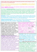
Electricity & Circuits notes (with specification points)
10.2
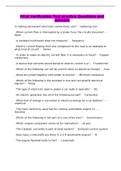
Name Function Symbol
Cell/battery Provides the circuit with a source of potential difference
A battery = 2 or more cells
Open switch Turns the circuit off
Closed switch Turns the circuit on (completes the circuit)
Voltmeter Used to measure voltage of a specific electrical component – attached
parallel to the component it needs to measure
Ammeter Used to measure current in a circuit. Connected in series with other
components
Resistor (fixed resistor) Reduces the flow of current. A fixed resistor has a resistance that can’t be
changed
Variable resistor Has a slider to change its resistance, often used in dimmer switches /
volume controls
Filament lamp N/A
Motor device that converts electrical energy to mechanical energy
Diode allows current to flow in one direction only. Used to convert AC to DC
current
Thermistors Its resistance depends on its temperature. Resistance decreases as
temperature increases vice versa
LDR (light-dependent Its resistance depends on the intensity of light, resistance decreases as
resistor) light intensity increases (in bright light) vice versa
LED (light-emitting diode) Same as a diode but emits light when a current passes through it. Used
for aviation lighting & displays e.g., road signs
Fuse Reduces risk of fires & electric shocks. The wire inside it melts if the
current passing through it increases beyond a point, which breaks the
circuit so electricity can no longer flow
a.c. supply Alternating current – the charges are always changing direction
d.c. supply Direct current – current in which the charges only move in one direction
Circuit diagrams:
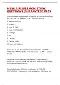
• Make sure the circuit is complete – all components should be connected properly for the circuit to work
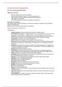
• Make sure that the terminals of the power supplies are aligned correctly (current flows from positive
terminals to negative terminals)
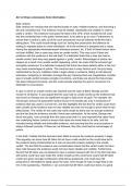
o If two cells are put in opposite ways, the current can’t flow so the circuit won’t work IMAGE
• An ammeter is connected in series, but a voltmeter is connected in parallel
10.3 - differences series parallel
in series & parallel
Current Same everywhere Splits at junctions
p.d. Voltage is shared between components Voltage across each component is the same
resistance Net resistance = sum of all resistance Net resistance is less than sum of resistance of
all components
10.5 - terminals of a cell make one end of the circuit positive and one end negative, setting up a p.d. across the
circuit. Potential difference = the amount of energy transferred per unit of charge passing through the terminals
p.d. is basically the amount of energy transferred per coulomb passing through a component. Therefore, 1V = 1J/C
10.4 - voltmeter measured the p.d. ‘across’ a component in Volts. It is connected in parallel to the component.
, 10.6 - V = J or W / Q
Some particles have charge, others don’t. Charge is measured in Coulombs. In 1 Coulomb, there are 6.25 x 10¹⁸
electrons.
10.8 - Electric current = rate of flow of charge = no. Of charged particles that pass a point every second. It is
measured in Amperes. In metals, current = rate of flow of electrons. 1A = 1000mA (milliAmps)
10.7 - Ammeter measures the current at a point in the circuit. It’s connected in series with a component
10.9 - I = Q/t - 1 Amp = 1 Coulomb per second, so 10A = 10C/s
10.10 - Current will flow in a circuit if there is 1. a p.d., 2. a closed circuit. Sources of potential difference =
cell/battery/electrical generator
10.11 - In a series circuit, the current is the same at any point. Because the no. Of electrons that passes through any
point in the circuit is the same.
However, at a junction, current is conserved (the amount of current flowing into the junction = the amount flowing
out because charge is conserved)
In metal wires, current is the rate of flow of electrons (negatively charged, so flow towards the positive terminal).
However, the Conventional current is the flow of positive charge from the positive terminal of a cell to the negative
terminal. This is the opposite to the direction of electron flow, but conventional current was defined before electric
current was discovered.
• 10.12 - 2 types of resistors: fixed resistor & variable resistor
• Fixed resistors have a resistance that remains constant - ohms, Ω
• Variable resistors can change the resistance by changing the length of wire that makes up the circuit
o A longer length of wire has more resistance than a shorter length of wire
• Resistance in a metal wire is caused by positive ions vibrating around fixed positions, restricting flow of
current
• Therefore, resistance increases = current decreases vice versa (for a given p.d.)
• Resistance in fixed & variable resistors aren’t affected by current. However, resistance of lamps, diodes,
LDRs and thermistors changes with the current going through it.
• 10.13 - Potential difference = current x resistance
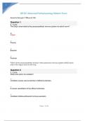
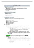
10.14 - if two resistors are connected in series, the net (total)
resistance increases (it is the sum of their individual resistances)
• Increasing the no. Of resistors increases overall resistance
because coulombs of charge have more resistors to pass
through, which increases no. Of collisions
• Total voltage = voltage of each of the components – voltage is
shared between all components
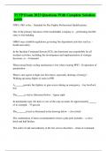
However, when resistors are connected in parallel, the net resistance decreases.
This is because there is now an extra route for current to flow, which causes current from the battery to increase,
meaning resistance decreases.
Advantages: Each component can be controlled individually, using their own switches. Also, if one component stops
working, the others will continue to function
10.15 - calculations with currents, p.d. & resistance in series circuits
• 10.16 - A series circuit has components connected in the same loop to a power supply
• Two disadvantages of series circuits are:
o If one of the components breaks, all the others will stop working
10.2
Name Function Symbol
Cell/battery Provides the circuit with a source of potential difference
A battery = 2 or more cells
Open switch Turns the circuit off
Closed switch Turns the circuit on (completes the circuit)
Voltmeter Used to measure voltage of a specific electrical component – attached
parallel to the component it needs to measure
Ammeter Used to measure current in a circuit. Connected in series with other
components
Resistor (fixed resistor) Reduces the flow of current. A fixed resistor has a resistance that can’t be
changed
Variable resistor Has a slider to change its resistance, often used in dimmer switches /
volume controls
Filament lamp N/A
Motor device that converts electrical energy to mechanical energy
Diode allows current to flow in one direction only. Used to convert AC to DC
current
Thermistors Its resistance depends on its temperature. Resistance decreases as
temperature increases vice versa
LDR (light-dependent Its resistance depends on the intensity of light, resistance decreases as
resistor) light intensity increases (in bright light) vice versa
LED (light-emitting diode) Same as a diode but emits light when a current passes through it. Used
for aviation lighting & displays e.g., road signs
Fuse Reduces risk of fires & electric shocks. The wire inside it melts if the
current passing through it increases beyond a point, which breaks the
circuit so electricity can no longer flow
a.c. supply Alternating current – the charges are always changing direction
d.c. supply Direct current – current in which the charges only move in one direction
Circuit diagrams:
• Make sure the circuit is complete – all components should be connected properly for the circuit to work
• Make sure that the terminals of the power supplies are aligned correctly (current flows from positive
terminals to negative terminals)
o If two cells are put in opposite ways, the current can’t flow so the circuit won’t work IMAGE
• An ammeter is connected in series, but a voltmeter is connected in parallel
10.3 - differences series parallel
in series & parallel
Current Same everywhere Splits at junctions
p.d. Voltage is shared between components Voltage across each component is the same
resistance Net resistance = sum of all resistance Net resistance is less than sum of resistance of
all components
10.5 - terminals of a cell make one end of the circuit positive and one end negative, setting up a p.d. across the
circuit. Potential difference = the amount of energy transferred per unit of charge passing through the terminals
p.d. is basically the amount of energy transferred per coulomb passing through a component. Therefore, 1V = 1J/C
10.4 - voltmeter measured the p.d. ‘across’ a component in Volts. It is connected in parallel to the component.
, 10.6 - V = J or W / Q
Some particles have charge, others don’t. Charge is measured in Coulombs. In 1 Coulomb, there are 6.25 x 10¹⁸
electrons.
10.8 - Electric current = rate of flow of charge = no. Of charged particles that pass a point every second. It is
measured in Amperes. In metals, current = rate of flow of electrons. 1A = 1000mA (milliAmps)
10.7 - Ammeter measures the current at a point in the circuit. It’s connected in series with a component
10.9 - I = Q/t - 1 Amp = 1 Coulomb per second, so 10A = 10C/s
10.10 - Current will flow in a circuit if there is 1. a p.d., 2. a closed circuit. Sources of potential difference =
cell/battery/electrical generator
10.11 - In a series circuit, the current is the same at any point. Because the no. Of electrons that passes through any
point in the circuit is the same.
However, at a junction, current is conserved (the amount of current flowing into the junction = the amount flowing
out because charge is conserved)
In metal wires, current is the rate of flow of electrons (negatively charged, so flow towards the positive terminal).
However, the Conventional current is the flow of positive charge from the positive terminal of a cell to the negative
terminal. This is the opposite to the direction of electron flow, but conventional current was defined before electric
current was discovered.
• 10.12 - 2 types of resistors: fixed resistor & variable resistor
• Fixed resistors have a resistance that remains constant - ohms, Ω
• Variable resistors can change the resistance by changing the length of wire that makes up the circuit
o A longer length of wire has more resistance than a shorter length of wire
• Resistance in a metal wire is caused by positive ions vibrating around fixed positions, restricting flow of
current
• Therefore, resistance increases = current decreases vice versa (for a given p.d.)
• Resistance in fixed & variable resistors aren’t affected by current. However, resistance of lamps, diodes,
LDRs and thermistors changes with the current going through it.
• 10.13 - Potential difference = current x resistance
10.14 - if two resistors are connected in series, the net (total)
resistance increases (it is the sum of their individual resistances)
• Increasing the no. Of resistors increases overall resistance
because coulombs of charge have more resistors to pass
through, which increases no. Of collisions
• Total voltage = voltage of each of the components – voltage is
shared between all components
However, when resistors are connected in parallel, the net resistance decreases.
This is because there is now an extra route for current to flow, which causes current from the battery to increase,
meaning resistance decreases.
Advantages: Each component can be controlled individually, using their own switches. Also, if one component stops
working, the others will continue to function
10.15 - calculations with currents, p.d. & resistance in series circuits
• 10.16 - A series circuit has components connected in the same loop to a power supply
• Two disadvantages of series circuits are:
o If one of the components breaks, all the others will stop working