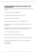
Load line analysis for a diode circuit (I versus VD)
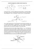
A plot of the current, I, versus the voltage drop across the diode, VD, will yield a straight
line, called the "Load Line", of possible values of current flow in the circuit. We form the
line by noting that I = 0 at VD = VS and that I = VD/(RS + RL) at VS = 0, as shown below:
The so called "Operating Point" is found through the second equation that relates I and
VD, namely the diode equation I = I0[exp(VD/KBT) - 1]. The I-V relation for the diode will
cross the Load Line at the Operation Point (open circle above). This provides a
graphical solution for the currents and voltages in a circuit with a diode.
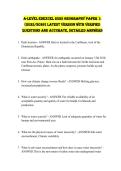
What happens when the source voltage changes with time, i.e., VS = VS(t)? Here the
Load Line varies with time; the slope is constant at dI/dV = -1/(RS + RL) while the
intercept shifts, as shown below. When VS(t) varies symmetrically around zero, as with
the AC line, we see that the maximum positive value of VS(t) leads to the maximum
current flow, while the maximum negative value of VS(t) leads to a minimal current, so
that asymptotically I(VS → -∞) → -I0. The rhythmic change in Operating Point (open
circles below) is the basis of the half-wave rectifier that you constructed.
A plot of the current, I, versus the voltage drop across the diode, VD, will yield a straight
line, called the "Load Line", of possible values of current flow in the circuit. We form the
line by noting that I = 0 at VD = VS and that I = VD/(RS + RL) at VS = 0, as shown below:
The so called "Operating Point" is found through the second equation that relates I and
VD, namely the diode equation I = I0[exp(VD/KBT) - 1]. The I-V relation for the diode will
cross the Load Line at the Operation Point (open circle above). This provides a
graphical solution for the currents and voltages in a circuit with a diode.
What happens when the source voltage changes with time, i.e., VS = VS(t)? Here the
Load Line varies with time; the slope is constant at dI/dV = -1/(RS + RL) while the
intercept shifts, as shown below. When VS(t) varies symmetrically around zero, as with
the AC line, we see that the maximum positive value of VS(t) leads to the maximum
current flow, while the maximum negative value of VS(t) leads to a minimal current, so
that asymptotically I(VS → -∞) → -I0. The rhythmic change in Operating Point (open
circles below) is the basis of the half-wave rectifier that you constructed.