theonlinephysicstutor.com
The diagram shows a network of four 2 Ω resistors.
1
The effective resistance, in Ω, between X and Y is
A 0.5
B 1.2
C 1.7
D 2.0
(Total 1 mark)
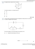
The circuit shown in the figure below shows an arrangement of resistors, W, X, Y, Z, connected
2 to a battery of negligible internal resistance.
The emf of the battery is 10V and the reading on the ammeter is 2.0 A.
(a) (i) Calculate the total resistance of the circuit.
answer = ..................................... Ω
(1)
@TOPhysicsTutor facebook.com/TheOnlinePhysicsTuto
Page 2 of 65
, theonlinephysicstutor.com
(ii) The resistors W, X, Y, and Z all have the same resistance. Show that your answer to
part (a) (i) is consistent with the resistance of each resistor being 3.0 Ω.
answer = ..................................... Ω
(3)
(b) (i) Calculate the current through resistor Y.
answer = ...................................... A
(2)
(ii) Calculate the pd across resistor W.
answer = ...................................... V
(2)
(Total 8 marks)
@TOPhysicsTutor facebook.com/TheOnlinePhysicsTuto
Page 3 of 65
, theonlinephysicstutor.com
A battery of e.m.f. 12 V and negligible internal resistance is connected to a resistor network as
3 shown in the circuit diagram.
(a) Calculate the total resistance of the circuit.
........................................................................................................................
........................................................................................................................
........................................................................................................................
........................................................................................................................
........................................................................................................................
(3)
(b) Calculate the current through the 50 Ω resistor.
........................................................................................................................
........................................................................................................................
(1)
(Total 4 marks)
@TOPhysicsTutor facebook.com/TheOnlinePhysicsTuto
Page 4 of 65
, theonlinephysicstutor.com
The diagram below shows an arrangement of resistors.
4
(a) Calculate the total resistance between terminals A and B.
answer = ................................................... Ω
(2)
(b) A potential difference is applied between the two terminals, A and B, and the power
dissipated in each of the 400 Ω resistors is 1.0 W.
(i) Calculate the potential difference across the 400 Ω resistors.
answer = ................................................... V
@TOPhysicsTutor facebook.com/TheOnlinePhysicsTuto
Page 5 of 65
The diagram shows a network of four 2 Ω resistors.
1
The effective resistance, in Ω, between X and Y is
A 0.5
B 1.2
C 1.7
D 2.0
(Total 1 mark)
The circuit shown in the figure below shows an arrangement of resistors, W, X, Y, Z, connected
2 to a battery of negligible internal resistance.
The emf of the battery is 10V and the reading on the ammeter is 2.0 A.
(a) (i) Calculate the total resistance of the circuit.
answer = ..................................... Ω
(1)
@TOPhysicsTutor facebook.com/TheOnlinePhysicsTuto
Page 2 of 65
, theonlinephysicstutor.com
(ii) The resistors W, X, Y, and Z all have the same resistance. Show that your answer to
part (a) (i) is consistent with the resistance of each resistor being 3.0 Ω.
answer = ..................................... Ω
(3)
(b) (i) Calculate the current through resistor Y.
answer = ...................................... A
(2)
(ii) Calculate the pd across resistor W.
answer = ...................................... V
(2)
(Total 8 marks)
@TOPhysicsTutor facebook.com/TheOnlinePhysicsTuto
Page 3 of 65
, theonlinephysicstutor.com
A battery of e.m.f. 12 V and negligible internal resistance is connected to a resistor network as
3 shown in the circuit diagram.
(a) Calculate the total resistance of the circuit.
........................................................................................................................
........................................................................................................................
........................................................................................................................
........................................................................................................................
........................................................................................................................
(3)
(b) Calculate the current through the 50 Ω resistor.
........................................................................................................................
........................................................................................................................
(1)
(Total 4 marks)
@TOPhysicsTutor facebook.com/TheOnlinePhysicsTuto
Page 4 of 65
, theonlinephysicstutor.com
The diagram below shows an arrangement of resistors.
4
(a) Calculate the total resistance between terminals A and B.
answer = ................................................... Ω
(2)
(b) A potential difference is applied between the two terminals, A and B, and the power
dissipated in each of the 400 Ω resistors is 1.0 W.
(i) Calculate the potential difference across the 400 Ω resistors.
answer = ................................................... V
@TOPhysicsTutor facebook.com/TheOnlinePhysicsTuto
Page 5 of 65