ES196 Statics and Structures
Truss Lab Report
u2216438, Date 30/11/2022
Abstract
The main aim of this experiment is to gain an in-depth understanding of trusses in different scenarios.
Three scenarios have been investigated: central load, angled load and combined load. Strain gauges
were attached to each member and results were collected in response to the loads. Calculations were
done to find the experimental and theoretical forces. In the analysis, it was found that vertical
members were in tension and angled members were in compression. Moreover, for the combined
load, both experimental results and superposition results were calculated. It showed that the
superposition results had a higher percentage error when compared to the experimental results.
Introduction
Trusses are used widely in civil engineering and are recognisable in bridges, roofs and other structures.
The reason why they are used is because of their ability to diffuse the forces from loads into the
ground. However, designing a truss is an impeccable part of the process because if it is designed wrong
then the structure could collapse. The main aim of this experiment is to gain a more in-depth
understanding of trusses and be able to calculate the forces involved.
Background Information
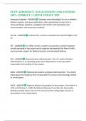
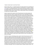
Figure 1 - shows the arrangement of a Howe truss [1]
There are many types of trusses, each with its own advantages and disadvantages. We will be focusing
on Howe trusses as shown in figure 1, which has a combination of horizontal, vertical and angled
chords. In addition, vertical members are in tension and the angled members are in compression [2].
Moreover, our truss will have a pin joint and a roller joint. A pin joint allows only rotation with two
reaction forces, whereas a roller joint allows both rotation and horizontal translation with only one
reaction force [3].
A strain gauge will be connected to each member to measure the strain and whether it is in
compression or tension. It measures the change in electrical resistance in relation to the force applied
[4]. Strain is defined as the applied stress caused to deform an element; in our experiment the strain
will cause the members to change in length. However, strain gauges can be affected by external factors
such as temperature, therefore four strain gauges will be connected to each member to compensate
for this.
To calculate the force from the strain we need to derive an equation:
First using the young’s modulus (𝐸) equation with components stress (𝜎) and strain (𝜀) in combination
with the stress (𝜎) equation with components force (𝐹) and area (𝐴).
! #
𝐸= 𝜎=
" $
𝐹
𝐸𝜀 =
𝐴
1
, 𝐹 = 𝐸𝜀𝐴
This equation will be used to find the experimental forces from the strains in the experiment.
The theoretical forces for each member can be calculated using the equilibrium equations, including
the horizontal forces (𝐹% ), the vertical forces (𝐹& ) and the moment (𝑀):
∑ 𝐹% = 0 ∑ 𝐹& = 0 ∑𝑀 = 0
First the global equilibrium of the entire truss can be calculated to find the values of the reaction forces
at the pin and roller joint. Then starting at the joints, isolating the node and using local equilibrium to
find the forces in the members. For local equilibrium, only two equilibrium equations will be sufficient
to calculate the forces. This method of finding theoretical forces is called the method of joints.
Method
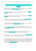
The truss lab setup is shown in figure 2, where you can see the Howe truss. The truss is loaded onto a
structures test frame (STR1) from TecQuipment. There are also wires connecting to four strain gauges,
attached in each member, to compensate for environmental factors such as temperature. The gauges
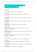
then connect to the strain gauge sensor and the digital strain display precise to 1µm. In figure 3, there
are two load cells (STR8A) from TecQuipment that can be attached, one in the middle in between
beam 9 and 10 and one at an angle on the right in between member 3 and 4. The load cells then
connect to a digital force display (STR1a) from TecQuipment precise to 1N. Moreover, member 1 is at
an angle of 30° in correspondence to the horizontal and the angled load, 𝑊' , is also at a 30°.
Furthermore, a pin joint can be seen on the left and a roller joint on the right.
Figure 2 – shows the truss lab setup from TecQuipment [5] Figure 3 – shows a diagram of the truss lab setup including
measurements needed for calculations [6]
Experiment 1
1. Turn all the equipment on and make sure all the equipment looks correct and nothing is
broken or faulty.
2. Connect load 𝑊( to the truss but make sure that it is not applying a load on the truss. Switch
the digital force display to channel 1 and calibrate if needed to 0N +/- 3N.
3. Moving onto the digital strain display, leaving 𝑊( with no load on the truss, go through
channels 1-13 and calibrate if need to 0µm +/- µm. At the same time, record the results for
strain for 0N for all the channels.
4. Now add a 100N load and record the results for strain for all the channels.
2
Truss Lab Report
u2216438, Date 30/11/2022
Abstract
The main aim of this experiment is to gain an in-depth understanding of trusses in different scenarios.
Three scenarios have been investigated: central load, angled load and combined load. Strain gauges
were attached to each member and results were collected in response to the loads. Calculations were
done to find the experimental and theoretical forces. In the analysis, it was found that vertical
members were in tension and angled members were in compression. Moreover, for the combined
load, both experimental results and superposition results were calculated. It showed that the
superposition results had a higher percentage error when compared to the experimental results.
Introduction
Trusses are used widely in civil engineering and are recognisable in bridges, roofs and other structures.
The reason why they are used is because of their ability to diffuse the forces from loads into the
ground. However, designing a truss is an impeccable part of the process because if it is designed wrong
then the structure could collapse. The main aim of this experiment is to gain a more in-depth
understanding of trusses and be able to calculate the forces involved.
Background Information
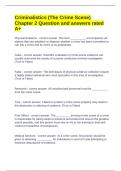
Figure 1 - shows the arrangement of a Howe truss [1]
There are many types of trusses, each with its own advantages and disadvantages. We will be focusing
on Howe trusses as shown in figure 1, which has a combination of horizontal, vertical and angled
chords. In addition, vertical members are in tension and the angled members are in compression [2].
Moreover, our truss will have a pin joint and a roller joint. A pin joint allows only rotation with two
reaction forces, whereas a roller joint allows both rotation and horizontal translation with only one
reaction force [3].
A strain gauge will be connected to each member to measure the strain and whether it is in
compression or tension. It measures the change in electrical resistance in relation to the force applied
[4]. Strain is defined as the applied stress caused to deform an element; in our experiment the strain
will cause the members to change in length. However, strain gauges can be affected by external factors
such as temperature, therefore four strain gauges will be connected to each member to compensate
for this.
To calculate the force from the strain we need to derive an equation:
First using the young’s modulus (𝐸) equation with components stress (𝜎) and strain (𝜀) in combination
with the stress (𝜎) equation with components force (𝐹) and area (𝐴).
! #
𝐸= 𝜎=
" $
𝐹
𝐸𝜀 =
𝐴
1
, 𝐹 = 𝐸𝜀𝐴
This equation will be used to find the experimental forces from the strains in the experiment.
The theoretical forces for each member can be calculated using the equilibrium equations, including
the horizontal forces (𝐹% ), the vertical forces (𝐹& ) and the moment (𝑀):
∑ 𝐹% = 0 ∑ 𝐹& = 0 ∑𝑀 = 0
First the global equilibrium of the entire truss can be calculated to find the values of the reaction forces
at the pin and roller joint. Then starting at the joints, isolating the node and using local equilibrium to
find the forces in the members. For local equilibrium, only two equilibrium equations will be sufficient
to calculate the forces. This method of finding theoretical forces is called the method of joints.
Method
The truss lab setup is shown in figure 2, where you can see the Howe truss. The truss is loaded onto a
structures test frame (STR1) from TecQuipment. There are also wires connecting to four strain gauges,
attached in each member, to compensate for environmental factors such as temperature. The gauges
then connect to the strain gauge sensor and the digital strain display precise to 1µm. In figure 3, there
are two load cells (STR8A) from TecQuipment that can be attached, one in the middle in between
beam 9 and 10 and one at an angle on the right in between member 3 and 4. The load cells then
connect to a digital force display (STR1a) from TecQuipment precise to 1N. Moreover, member 1 is at
an angle of 30° in correspondence to the horizontal and the angled load, 𝑊' , is also at a 30°.
Furthermore, a pin joint can be seen on the left and a roller joint on the right.
Figure 2 – shows the truss lab setup from TecQuipment [5] Figure 3 – shows a diagram of the truss lab setup including
measurements needed for calculations [6]
Experiment 1
1. Turn all the equipment on and make sure all the equipment looks correct and nothing is
broken or faulty.
2. Connect load 𝑊( to the truss but make sure that it is not applying a load on the truss. Switch
the digital force display to channel 1 and calibrate if needed to 0N +/- 3N.
3. Moving onto the digital strain display, leaving 𝑊( with no load on the truss, go through
channels 1-13 and calibrate if need to 0µm +/- µm. At the same time, record the results for
strain for 0N for all the channels.
4. Now add a 100N load and record the results for strain for all the channels.
2