Smart
Transformers
________________________________________________________________________________
Date: 30 May 2022
________________________________________________________________________________
Abstract: A Smart Transformer (ST), also known as a Solid-State Transformer, is
made up of powerful semiconductor components, control circuitry, and conventional
high frequency transformers. The advancement of semiconductor technology has
provided a new alternative to conventional transformer technology by providing a
more elegant solution using Smart Transformers (ST). It switches the voltage ratio
based on semiconductor technology. By combining high power density and high
frequency, STs provide additional flexibility to control power distribution networks,
thereby facilitating the smooth conversion of AC to DC and DC to AC, as required.
This has given researchers, worldwide, a new opportunity to suggest new topologies,
to use new materials and to experiment in varied environments. The smart
transformers are used to provide extra flexibility to control power distribution
networks, thereby facilitating the smooth conversion of AC to DC and DC to AC, as
required.
1. Background theory
Smart transformers (STs) form the initial building blocks 1.2. Disadvantages and Technology challenges
of developing smart cities. ST were developed around
1950s by researchers. STs were developed as a Production
fundamental element to overcome challenges in the STs will not likely be mass produced in the short
ecosystem of smart grid. Smart transformers were term, and they are expected to be installed in only
designed to replace conventional transformers(CT) which a few power grid nodes
operate at low frequency(50Hz), bulky and heavy at the Costs
same time. The usage of CTs in the electrical grid exposes STs provides a wide range of new functionalities that
the electrical grid to variety of problems like uneven power create working conditions that are very different from
flow, harmonics, and voltage, frequency instability etc. As those of a standard transformer, hence it will not be
a result of the CT restrictions, serious difficulties in the cheap to manufacture them.
grid emerge, necessitating a dramatic solution [1] Distribution grids
The temperature of the power semiconductors inside
1.1. Advantages of smart transformers(STs) the ST is very changeable because to the highly
dynamic power profiles and frequent contingencies,
Reduction of the transformer volume and weight due such as faults and inrush currents, that define modern
to high operational frequency (> 1 kHz). distribution grids. This temperature excursion causes
The automatic voltage regulation and congestion line mechanical fatigue in the packing, which eventually
controls that improve distribution management. leads to failures, potentially making a power-
The use of galvanic isolation to produce voltage electronics-based transformer unsuitable for
change. distribution grids.
The establishment of a bidirectional communication Efficiency and reliability
channel for the purposes of control, surveillance, and The ST must compete with an existing technology, the
the enhancement of safety, efficiency, dependability, traditional transformers making it even more difficult
and interactivity. Reduced flows and current losses in to meet efficiency and reliability requirements.
distribution lines, as well as harmonic reduction.
The immediate decrease of energy uses through the 1.3. Design of smart transformer
provision of a consistent and optimal supply.
The ability to connect storage devices to renewable
energy sources and a variety of loads in a bidirectional
energy flow.
The protection of electrical equipment from power
fluctuations, which increases their lifetimes.
1
, A smart grid's smart protection system is a subsystem that
delivers sophisticated grid reliability analysis, failure
protection, as well as security and privacy protection
services. The smart grid must not only achieve a smarter
management system, but also a smarter protection system
that can more effectively and efficiently support failure
prevention mechanisms, handle cyber security challenges,
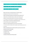
Figure 1Intergrated Smart Transformer [2]
and safeguard privacy by leveraging smart infrastructure.
As shown in Figure 1 above, status sensors and electronic Protective relays are built in such a way that they can
sensors are integrated with the transformer body, and the immediately detect and isolate a failure while causing
use of a standard mechanical and electrical interface minimal disruption to the unaffected areas [3].
allows for smooth sensor replacement from multiple
manufacturers, considerably improving equipment Overload protection
serviceability. To achieve automatic and smart transformer A standard AC transformer must survive overloading
control, the operating mechanism and its control interface conditions for a limited amount of time at the expense of
are designed to be integrated with the transformer body. solid insulation life, and the maximum allowable peak
For an informative, interactive, and digital smart overloading for distribution transformers can be as high as
transformer and its data fusing capabilities, smart 300 % of the rated loading [8]. Smart transformer
components are combined with the transformer body [2]. overloading design aims for a realistic overloading
capability of 120 % to 150 % due to the thermal breakdown
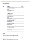
Winding fibre temperature sensors, dissolved gas in oil limit of power electronic components [4].
sensors, ultra-high frequency partial discharge (UHFPD)
sensors, high frequency partial discharge (HFPD) sensors, ST Failure Due to Overheating
core earthing current sensors, oil temperature sensors, and
oil pressure sensors are among the status sensors in a smart The biggest risk of overloading is that the power electrical
transformer, with four types (winding fiber temperature devices will overheat and fail. The current in the device
sensors, UHFPD sensors, oil temperature sensors, and oil causes losses proportional to the current's magnitude, and
pressure sensors) falling under the internal sensor category these losses cause the device junction temperature to rise
and the other three falling under the external sensor [4]. To prevent this a thermal model is used. ST thermal
category. Figure 2 schematically depicts the combined model uses a maximum junction temperature of 150 ℃ to
design of transformers and sensors [2]. account for differences in loss distribution and thermal
impedance from one device to the next, which could result
in hot spots in specific devices.
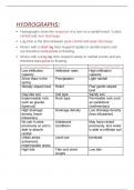
Figure 3 shows the ST thermal model, which includes the
switching device and heat sink. The average losses of the
power electronic devices in the ST are used as an input in
this model. Between the switching devices and the heat
sink, the switching devices are also represented as a
thermal capacitance with a thermal resistance. The heat
sink is described as a thermal capacitance with a thermal
resistance to the ambient environment, with a temperature
of 50 degrees Celsius assumed [4].
Figure 2The integrated design of transformers and sensors
[2]
Figure 3Thermal Model of ST Rectifier [4]
From the figure above we can see Inside the transformer The TIPS was modelled in a simplified grid system to
tank, temperature sensors are installed on the top and assess how much power, voltage, and current the TIPS
bottom. Sensors for UHFPD are mounted on the tank's top processed under various overloaded scenarios. The losses
or around the internal walls. On the upper side of the in the TIPS devices as a function of the current through
cabinet wall, oil pressure sensors are mounted. A cycle them were determined using a loss model, and these losses
path is formed by connecting dissolved gas in oil sensors were then entered into the thermal model mentioned
to the oil outflow and return. On the core grounding bronze above. Figure 4 shows the device junction temperature at
plate, current sensors and HFPD sensors are placed [2]. a 140 % overloading scenario, which shows that the
junction temperature climbs to just under the 150 ℃ limit.
1.4. Protection This confirms the 140 % overloaded concept from the
beginning [5].
2
, filter in this design is a series R - L branch per phase, where
R is very small. When determining the basic insulation
level (BIL) of a distribution transformer, lightning-induced
overvoltage is usually taken into account. After the input
filter, a metal oxide varistor (MOV) based surge arrester
should be considered to protect the power electronics
devices in the STs [5].
Over current relay protection
Figure 4 : TIPS Rectifier Temperature for a 1.4 p.u. In a radial distribution, an overcurrent relay is usually
Overloading [5] utilized to protect the system components. It's also one of
the simplest forms of protection. The overcurrent relay's
ST Operation Multifunctioning due to Protective operation is depicted in Figure 5.
Shutdown of the Rectifier Stage Controller
An average model of the ST rectifier stage was used to test
the ST controller's safety against excessive temperature
rise. The controller limitations were set to prevent the ST
devices from exceeding their thermal limits. Current
saturation restrictions are implemented in the ST
controllers to provide this protection. [5]
The controlled power load in this model pulls the set
overloading power. This power comes from the DC bus
capacitor, which starts to discharge as its voltage drops. To Figure 5 overcurrent relay [3]
manage the DC bus voltage, the rectifier controller detects
a drop in DC bus voltage and increases the power drawn
from the grid. The rectifier's saturation limits will Under normal operation: 𝐼’ < 𝐼
eventually be reached, and it will no longer be able to Under normal operation, there is no trip signal therefore
provide enough power to balance the DC bus voltage [4]. the circuit breaker (CB) is closed
The voltage will collapse at this point, and once it falls Short Circuit fault: 𝐼’ > 𝐼
below the minimum, the entire TIPS will enter a controlled
When the secondary current of the transformer is greater
shutdown. This is referred to as protective load shedding
than the pick-up current, there is a trip signal and therefore
because it prevents an excessive temperature rise during an
CB will open and isolate the line
overloading state. This not only protects the gadgets, but
also demonstrates that the ST will not perform under
Overcurrent relays are divided into two categories,
extreme overloading [4].
Instantaneous overcurrent relay and time-overcurrent.
When it goes beyond the relay an instantaneous
Over voltage protection
overcurrent relay is designed in such a way that there is no
time delay in the action. The operational time can vary
Large transient over voltages, such as those induced by
drastically. The period can be as short as 0.016 seconds or
lightning strikes, pose a number of dangers to the TIPS'
as long as 0.1 seconds, and time-overcurrent relays have
power electronics. To begin with, overvoltage can cause
an operating characteristic in which their running time
the devices' collector to emitter voltage limitations to be
varies inversely with their current [3].
exceeded, resulting in an avalanche breakdown that
normally destroys the device. Second, the high-frequency
Directional Relay Protection
voltage oscillations created by the overvoltage could
The directional protection works on the same premise as
trigger the gates of the turned-off devices, resulting in a
the overcurrent protection, except it allows you to choose
short across the dc-bus capacitors and the devices'
whether you want to go forward or backward. Parallel lines
destruction [4].
are the most common application for this form of
protection. It can be used to detect ground and phase
Third, the voltage generated between a component and
problems as well. Current, voltage, and the angle between
ground, such as an IGBT terminal and a grounded heat
current and voltage are the values required for this form of
sink, may cause the insulation between that component and
protection. To determine the direction of the fault, an
ground to fail. Finally, transient overvoltage can result in
Intelligent Electronic Device (IED) is required to compare
significant ground currents flowing through switching
the system's line current with the fault current. This is
devices, potentially exceeding the junction temperature
referred to as polarizing quality [3].
limit of the devices [4].
Differential Relay Protection
STs normally consider similar overvoltage protection
Differential relay protection uses principle of Kirchhoff’s
levels as conventional transformers. The ST input filter can
current law. It signifies that the sum of the currents
be designed to minimize grid voltage transients. The input
3
Transformers
________________________________________________________________________________
Date: 30 May 2022
________________________________________________________________________________
Abstract: A Smart Transformer (ST), also known as a Solid-State Transformer, is
made up of powerful semiconductor components, control circuitry, and conventional
high frequency transformers. The advancement of semiconductor technology has
provided a new alternative to conventional transformer technology by providing a
more elegant solution using Smart Transformers (ST). It switches the voltage ratio
based on semiconductor technology. By combining high power density and high
frequency, STs provide additional flexibility to control power distribution networks,
thereby facilitating the smooth conversion of AC to DC and DC to AC, as required.
This has given researchers, worldwide, a new opportunity to suggest new topologies,
to use new materials and to experiment in varied environments. The smart
transformers are used to provide extra flexibility to control power distribution
networks, thereby facilitating the smooth conversion of AC to DC and DC to AC, as
required.
1. Background theory
Smart transformers (STs) form the initial building blocks 1.2. Disadvantages and Technology challenges
of developing smart cities. ST were developed around
1950s by researchers. STs were developed as a Production
fundamental element to overcome challenges in the STs will not likely be mass produced in the short
ecosystem of smart grid. Smart transformers were term, and they are expected to be installed in only
designed to replace conventional transformers(CT) which a few power grid nodes
operate at low frequency(50Hz), bulky and heavy at the Costs
same time. The usage of CTs in the electrical grid exposes STs provides a wide range of new functionalities that
the electrical grid to variety of problems like uneven power create working conditions that are very different from
flow, harmonics, and voltage, frequency instability etc. As those of a standard transformer, hence it will not be
a result of the CT restrictions, serious difficulties in the cheap to manufacture them.
grid emerge, necessitating a dramatic solution [1] Distribution grids
The temperature of the power semiconductors inside
1.1. Advantages of smart transformers(STs) the ST is very changeable because to the highly
dynamic power profiles and frequent contingencies,
Reduction of the transformer volume and weight due such as faults and inrush currents, that define modern
to high operational frequency (> 1 kHz). distribution grids. This temperature excursion causes
The automatic voltage regulation and congestion line mechanical fatigue in the packing, which eventually
controls that improve distribution management. leads to failures, potentially making a power-
The use of galvanic isolation to produce voltage electronics-based transformer unsuitable for
change. distribution grids.
The establishment of a bidirectional communication Efficiency and reliability
channel for the purposes of control, surveillance, and The ST must compete with an existing technology, the
the enhancement of safety, efficiency, dependability, traditional transformers making it even more difficult
and interactivity. Reduced flows and current losses in to meet efficiency and reliability requirements.
distribution lines, as well as harmonic reduction.
The immediate decrease of energy uses through the 1.3. Design of smart transformer
provision of a consistent and optimal supply.
The ability to connect storage devices to renewable
energy sources and a variety of loads in a bidirectional
energy flow.
The protection of electrical equipment from power
fluctuations, which increases their lifetimes.
1
, A smart grid's smart protection system is a subsystem that
delivers sophisticated grid reliability analysis, failure
protection, as well as security and privacy protection
services. The smart grid must not only achieve a smarter
management system, but also a smarter protection system
that can more effectively and efficiently support failure
prevention mechanisms, handle cyber security challenges,
Figure 1Intergrated Smart Transformer [2]
and safeguard privacy by leveraging smart infrastructure.
As shown in Figure 1 above, status sensors and electronic Protective relays are built in such a way that they can
sensors are integrated with the transformer body, and the immediately detect and isolate a failure while causing
use of a standard mechanical and electrical interface minimal disruption to the unaffected areas [3].
allows for smooth sensor replacement from multiple
manufacturers, considerably improving equipment Overload protection
serviceability. To achieve automatic and smart transformer A standard AC transformer must survive overloading
control, the operating mechanism and its control interface conditions for a limited amount of time at the expense of
are designed to be integrated with the transformer body. solid insulation life, and the maximum allowable peak
For an informative, interactive, and digital smart overloading for distribution transformers can be as high as
transformer and its data fusing capabilities, smart 300 % of the rated loading [8]. Smart transformer
components are combined with the transformer body [2]. overloading design aims for a realistic overloading
capability of 120 % to 150 % due to the thermal breakdown
Winding fibre temperature sensors, dissolved gas in oil limit of power electronic components [4].
sensors, ultra-high frequency partial discharge (UHFPD)
sensors, high frequency partial discharge (HFPD) sensors, ST Failure Due to Overheating
core earthing current sensors, oil temperature sensors, and
oil pressure sensors are among the status sensors in a smart The biggest risk of overloading is that the power electrical
transformer, with four types (winding fiber temperature devices will overheat and fail. The current in the device
sensors, UHFPD sensors, oil temperature sensors, and oil causes losses proportional to the current's magnitude, and
pressure sensors) falling under the internal sensor category these losses cause the device junction temperature to rise
and the other three falling under the external sensor [4]. To prevent this a thermal model is used. ST thermal
category. Figure 2 schematically depicts the combined model uses a maximum junction temperature of 150 ℃ to
design of transformers and sensors [2]. account for differences in loss distribution and thermal
impedance from one device to the next, which could result
in hot spots in specific devices.
Figure 3 shows the ST thermal model, which includes the
switching device and heat sink. The average losses of the
power electronic devices in the ST are used as an input in
this model. Between the switching devices and the heat
sink, the switching devices are also represented as a
thermal capacitance with a thermal resistance. The heat
sink is described as a thermal capacitance with a thermal
resistance to the ambient environment, with a temperature
of 50 degrees Celsius assumed [4].
Figure 2The integrated design of transformers and sensors
[2]
Figure 3Thermal Model of ST Rectifier [4]
From the figure above we can see Inside the transformer The TIPS was modelled in a simplified grid system to
tank, temperature sensors are installed on the top and assess how much power, voltage, and current the TIPS
bottom. Sensors for UHFPD are mounted on the tank's top processed under various overloaded scenarios. The losses
or around the internal walls. On the upper side of the in the TIPS devices as a function of the current through
cabinet wall, oil pressure sensors are mounted. A cycle them were determined using a loss model, and these losses
path is formed by connecting dissolved gas in oil sensors were then entered into the thermal model mentioned
to the oil outflow and return. On the core grounding bronze above. Figure 4 shows the device junction temperature at
plate, current sensors and HFPD sensors are placed [2]. a 140 % overloading scenario, which shows that the
junction temperature climbs to just under the 150 ℃ limit.
1.4. Protection This confirms the 140 % overloaded concept from the
beginning [5].
2
, filter in this design is a series R - L branch per phase, where
R is very small. When determining the basic insulation
level (BIL) of a distribution transformer, lightning-induced
overvoltage is usually taken into account. After the input
filter, a metal oxide varistor (MOV) based surge arrester
should be considered to protect the power electronics
devices in the STs [5].
Over current relay protection
Figure 4 : TIPS Rectifier Temperature for a 1.4 p.u. In a radial distribution, an overcurrent relay is usually
Overloading [5] utilized to protect the system components. It's also one of
the simplest forms of protection. The overcurrent relay's
ST Operation Multifunctioning due to Protective operation is depicted in Figure 5.
Shutdown of the Rectifier Stage Controller
An average model of the ST rectifier stage was used to test
the ST controller's safety against excessive temperature
rise. The controller limitations were set to prevent the ST
devices from exceeding their thermal limits. Current
saturation restrictions are implemented in the ST
controllers to provide this protection. [5]
The controlled power load in this model pulls the set
overloading power. This power comes from the DC bus
capacitor, which starts to discharge as its voltage drops. To Figure 5 overcurrent relay [3]
manage the DC bus voltage, the rectifier controller detects
a drop in DC bus voltage and increases the power drawn
from the grid. The rectifier's saturation limits will Under normal operation: 𝐼’ < 𝐼
eventually be reached, and it will no longer be able to Under normal operation, there is no trip signal therefore
provide enough power to balance the DC bus voltage [4]. the circuit breaker (CB) is closed
The voltage will collapse at this point, and once it falls Short Circuit fault: 𝐼’ > 𝐼
below the minimum, the entire TIPS will enter a controlled
When the secondary current of the transformer is greater
shutdown. This is referred to as protective load shedding
than the pick-up current, there is a trip signal and therefore
because it prevents an excessive temperature rise during an
CB will open and isolate the line
overloading state. This not only protects the gadgets, but
also demonstrates that the ST will not perform under
Overcurrent relays are divided into two categories,
extreme overloading [4].
Instantaneous overcurrent relay and time-overcurrent.
When it goes beyond the relay an instantaneous
Over voltage protection
overcurrent relay is designed in such a way that there is no
time delay in the action. The operational time can vary
Large transient over voltages, such as those induced by
drastically. The period can be as short as 0.016 seconds or
lightning strikes, pose a number of dangers to the TIPS'
as long as 0.1 seconds, and time-overcurrent relays have
power electronics. To begin with, overvoltage can cause
an operating characteristic in which their running time
the devices' collector to emitter voltage limitations to be
varies inversely with their current [3].
exceeded, resulting in an avalanche breakdown that
normally destroys the device. Second, the high-frequency
Directional Relay Protection
voltage oscillations created by the overvoltage could
The directional protection works on the same premise as
trigger the gates of the turned-off devices, resulting in a
the overcurrent protection, except it allows you to choose
short across the dc-bus capacitors and the devices'
whether you want to go forward or backward. Parallel lines
destruction [4].
are the most common application for this form of
protection. It can be used to detect ground and phase
Third, the voltage generated between a component and
problems as well. Current, voltage, and the angle between
ground, such as an IGBT terminal and a grounded heat
current and voltage are the values required for this form of
sink, may cause the insulation between that component and
protection. To determine the direction of the fault, an
ground to fail. Finally, transient overvoltage can result in
Intelligent Electronic Device (IED) is required to compare
significant ground currents flowing through switching
the system's line current with the fault current. This is
devices, potentially exceeding the junction temperature
referred to as polarizing quality [3].
limit of the devices [4].
Differential Relay Protection
STs normally consider similar overvoltage protection
Differential relay protection uses principle of Kirchhoff’s
levels as conventional transformers. The ST input filter can
current law. It signifies that the sum of the currents
be designed to minimize grid voltage transients. The input
3