Unit 6 DC Circuit Theory/ Measurement & Diodes Assignment 2
In this assignment I will be comparing the
forward & reverse characteristics of 2
different types of semi-conductor diodes.
Firstly, a transformer is an immobile device
that converts electrical energy from one
circuit to another without any direct electrical
connection, & with the support of related
induction between two windings. Essentially,
it transforms power from one circuit to the
other without altering its frequency, but it
may have a different voltage level.
There are a variety of different types of
transformers, but I will be focusing only on
two; Step Up & Step Down Transformer &
Core Type & Shell Type Transformer.
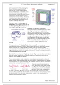
Beginning with the step up & step down
transformer, which is used for stepping up & down
the voltage level of power in transmission &
dispersal power system network. In a core type
transformer, it consists of 2 limbs with 2 horizontal
sections known as yoke. The shape of the core is a
rectangle with a magnetic circuit with cylindrical
coils is placed on both the limbs. In a shell type
transformer, there is a central limb with two outer
limbs; both cylindrical coils are placed on the
central limb, & a double magnetic circuit is
involved.
Moving onwards to a P-N Junction Diode, which is essentially two terminals or
semiconductors that allows the electric current in only one direction, known as the forward
bias, & the reverse bias is when it blocks the current in the other direction. N-type
semiconductors are basically free electrons that are the majority charge carriers, but with p-
type semiconductors, holes are the majority charge carries. To create a p-n junction p-type &
n-type semiconductors must be joined.
Essentially biasing is the process of applying external voltage to a p-n junction semiconductor
diode; the external voltage to the p-n junction diode has two methods of which it can be
applied to: Forward & Reverse Biasing.
The p-n junction diode is simply created from semiconductor materials, such as silicon &
gallium arsenide. When designing diodes, the silicon material is more preferred over gallium
as silicon functions at a higher temperature. The symbol for what a p-n junction looks like on
a forward bias & reverse bias is shown below.
When the diode is forward biased, this
shows the direction of the electric current
as it allows the current to flow; the p-type
semiconductor is joined to the cathode of
the battery, & the n-type is connected to
the anode of the battery. But when it’s reverse biased, it shows the holes that move from
anode to cathode, which is the direction of the current. If the diode is reverse biased, it blocks
the electric current’s flow; the p-type semiconductor is joined to the cathode side of the
battery & the anode side of the battery.
P3 Fahim Mohammed
In this assignment I will be comparing the
forward & reverse characteristics of 2
different types of semi-conductor diodes.
Firstly, a transformer is an immobile device
that converts electrical energy from one
circuit to another without any direct electrical
connection, & with the support of related
induction between two windings. Essentially,
it transforms power from one circuit to the
other without altering its frequency, but it
may have a different voltage level.
There are a variety of different types of
transformers, but I will be focusing only on
two; Step Up & Step Down Transformer &
Core Type & Shell Type Transformer.
Beginning with the step up & step down
transformer, which is used for stepping up & down
the voltage level of power in transmission &
dispersal power system network. In a core type
transformer, it consists of 2 limbs with 2 horizontal
sections known as yoke. The shape of the core is a
rectangle with a magnetic circuit with cylindrical
coils is placed on both the limbs. In a shell type
transformer, there is a central limb with two outer
limbs; both cylindrical coils are placed on the
central limb, & a double magnetic circuit is
involved.
Moving onwards to a P-N Junction Diode, which is essentially two terminals or
semiconductors that allows the electric current in only one direction, known as the forward
bias, & the reverse bias is when it blocks the current in the other direction. N-type
semiconductors are basically free electrons that are the majority charge carriers, but with p-
type semiconductors, holes are the majority charge carries. To create a p-n junction p-type &
n-type semiconductors must be joined.
Essentially biasing is the process of applying external voltage to a p-n junction semiconductor
diode; the external voltage to the p-n junction diode has two methods of which it can be
applied to: Forward & Reverse Biasing.
The p-n junction diode is simply created from semiconductor materials, such as silicon &
gallium arsenide. When designing diodes, the silicon material is more preferred over gallium
as silicon functions at a higher temperature. The symbol for what a p-n junction looks like on
a forward bias & reverse bias is shown below.
When the diode is forward biased, this
shows the direction of the electric current
as it allows the current to flow; the p-type
semiconductor is joined to the cathode of
the battery, & the n-type is connected to
the anode of the battery. But when it’s reverse biased, it shows the holes that move from
anode to cathode, which is the direction of the current. If the diode is reverse biased, it blocks
the electric current’s flow; the p-type semiconductor is joined to the cathode side of the
battery & the anode side of the battery.
P3 Fahim Mohammed