Chapters 2 - 20 Covered
SOLUTIONS
@LECTJULIESOLUTIONSSTUVIA
,Table of Contents
PART 1
2 Formulation of the equations of motion: Single-degree-
of- freedom systems
3 Formulation of the equations of motion: Multi-degree-
of- freedom systems
4 Principles of analytical
mechanics PART 2
5 Free vibration response: Single-degree-of-freedom system
6 Forced harmonic vibrations: Single-degree-of-
freedom system
7 Response to general dynamic loading and transient
response
8 Analysis of single-degree-of-freedom systems:
Approximate and numerical methods
9 Analysis of response in the frequency
domain PART 3
10 Free vibration response: Multi-degree-of-freedom system
11 Numerical solution of the eigenproblem
,12 Forced dynamic response: Multi-degree-of-
freedom systems
13 Analysis of multi-degree-of-freedom systems:
Approximate and numerical methods
PART 4
14 Formulation of the equations of motion:
Continuous systems
15 Continuous systems: Free vibration response
16 Continuous systems: Forced-vibration response
17 Wave propagation
analysis PART 5
18 Finite element method
19 Component mode synthesis
20 Analysis of nonlinear response
@LECTJULIESOLUTIONSSTUVIA
, Chapter 2 In a similar manner we get
Problem 2.1 Iy = M ü y
90 N/mm 60 N/mm For an angular acceleration θ ¨ about the center
of mass the inertia force on the infinitesimal ele-
ment is directed along the tangent and is γr2θ ¨dθdr.
u The x component of this force is γr2θ¨dθdr sin θ.
It is easily seen that the resultant of all x direc-
tion forces is zero. In a similar manner the resul-
40 N/mm tant y direction force is zero. However, a clockwise
moment about the center of the disc exists and is
Figure S2.1 given by
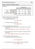
Referring to Figure S2.1 the springs with stiff- ∫ R ∫ 2π
R2 ¨ 2
ness 60 N/mm and 90 N/mm are placed in series Mθ = γθ¨r3dθdr = γπR2 θ = M R θ¨
and have an effective stiffness given by 0 0 2 2
1 The elliptical plate shown in Figure S2.2(c) is
k1 = = 36 N/mm
1/60+ 1/90 divided into the infinitesimal elements as shown.
The mass of an element is γdxdy and the inertia
This combination is now placed in parallel with the
force acting on it when the disc undergoes trans-
spring of stiffness 40 N/mm giving a final effective
lation in the x direction with acceleration ü x is
stiffness of
γ üx dxdy. The resultant inertia force in the neg-
keff = k1 + 40 = 76 N/mm ative x direction is given by
∫a/2 ∫ √ 2 2
b/2 1−4x /a
Problem 2.2 Ix = √ 2
γüy dydx
−a/2 −b/2 1−4x 2/a
∫ a/2 √
= γ ü x b 1 − 4x2/a2dx
dxdy −a/2
dr πγab
dθ R = = M ü x
b
4
The moment of the x direction inertia force on an
element is γ üx y dxdy. The resultant moment ob-
a tained over the area is zero. The inertia force pro-
(a) (b)
duced by an acceleration in the y direction is ob-
tained in a similar manner and is M ü y directed in
the negative y direction.
Figure
S2.2 An angular acceleration θ ¨ produces a clockwise
The infinitesimal area shown in Figure S2.2(a) moment equal to γr2θ¨dxdy = γ x2 + y2 θ¨dxdy.
is equal to rdθdr. When the circular disc moves Integration over the area yields the resultant mo-
in the x direction with acceleration ü x the inertia ment, which is clockwise
force on the infinitesimal are is γrdθdrüx , where γ
√
ids the mass per unit area. The resultant inertia ∫ a/2 ∫ b/2 1−4x2/a2
force on the disc acting in the negative x direction Iθ √ γθ¨ x2 + dydx
2
= 2 2
y
is given by −a/2 −b/2 1−4x /a
2 2 2 2
∫R∫ 2π πab a + b ¨ a +b ¨
=γ θ =M θ
Ix = γü x rdθdr = γπR2 ü x = M ü x 4 16 16
0 0
where M is the total mass of the disc. The resultant The x and y direction inertia forces produced on
moment of the inertia forces about the centre of the the infinitesimal element are —γθ ¨sin θdxdy and
disc, which is also the centre of mass is given by γθ¨cos θdxdy, respectively. When summed over the
∫ R ∫ 2π area the net forces produced by these are easily
shown to be zero.
Mx = γ üx r 2 sin θdθdr = 0
0 0
SOLUTIONS
@LECTJULIESOLUTIONSSTUVIA
,Table of Contents
PART 1
2 Formulation of the equations of motion: Single-degree-
of- freedom systems
3 Formulation of the equations of motion: Multi-degree-
of- freedom systems
4 Principles of analytical
mechanics PART 2
5 Free vibration response: Single-degree-of-freedom system
6 Forced harmonic vibrations: Single-degree-of-
freedom system
7 Response to general dynamic loading and transient
response
8 Analysis of single-degree-of-freedom systems:
Approximate and numerical methods
9 Analysis of response in the frequency
domain PART 3
10 Free vibration response: Multi-degree-of-freedom system
11 Numerical solution of the eigenproblem
,12 Forced dynamic response: Multi-degree-of-
freedom systems
13 Analysis of multi-degree-of-freedom systems:
Approximate and numerical methods
PART 4
14 Formulation of the equations of motion:
Continuous systems
15 Continuous systems: Free vibration response
16 Continuous systems: Forced-vibration response
17 Wave propagation
analysis PART 5
18 Finite element method
19 Component mode synthesis
20 Analysis of nonlinear response
@LECTJULIESOLUTIONSSTUVIA
, Chapter 2 In a similar manner we get
Problem 2.1 Iy = M ü y
90 N/mm 60 N/mm For an angular acceleration θ ¨ about the center
of mass the inertia force on the infinitesimal ele-
ment is directed along the tangent and is γr2θ ¨dθdr.
u The x component of this force is γr2θ¨dθdr sin θ.
It is easily seen that the resultant of all x direc-
tion forces is zero. In a similar manner the resul-
40 N/mm tant y direction force is zero. However, a clockwise
moment about the center of the disc exists and is
Figure S2.1 given by
Referring to Figure S2.1 the springs with stiff- ∫ R ∫ 2π
R2 ¨ 2
ness 60 N/mm and 90 N/mm are placed in series Mθ = γθ¨r3dθdr = γπR2 θ = M R θ¨
and have an effective stiffness given by 0 0 2 2
1 The elliptical plate shown in Figure S2.2(c) is
k1 = = 36 N/mm
1/60+ 1/90 divided into the infinitesimal elements as shown.
The mass of an element is γdxdy and the inertia
This combination is now placed in parallel with the
force acting on it when the disc undergoes trans-
spring of stiffness 40 N/mm giving a final effective
lation in the x direction with acceleration ü x is
stiffness of
γ üx dxdy. The resultant inertia force in the neg-
keff = k1 + 40 = 76 N/mm ative x direction is given by
∫a/2 ∫ √ 2 2
b/2 1−4x /a
Problem 2.2 Ix = √ 2
γüy dydx
−a/2 −b/2 1−4x 2/a
∫ a/2 √
= γ ü x b 1 − 4x2/a2dx
dxdy −a/2
dr πγab
dθ R = = M ü x
b
4
The moment of the x direction inertia force on an
element is γ üx y dxdy. The resultant moment ob-
a tained over the area is zero. The inertia force pro-
(a) (b)
duced by an acceleration in the y direction is ob-
tained in a similar manner and is M ü y directed in
the negative y direction.
Figure
S2.2 An angular acceleration θ ¨ produces a clockwise
The infinitesimal area shown in Figure S2.2(a) moment equal to γr2θ¨dxdy = γ x2 + y2 θ¨dxdy.
is equal to rdθdr. When the circular disc moves Integration over the area yields the resultant mo-
in the x direction with acceleration ü x the inertia ment, which is clockwise
force on the infinitesimal are is γrdθdrüx , where γ
√
ids the mass per unit area. The resultant inertia ∫ a/2 ∫ b/2 1−4x2/a2
force on the disc acting in the negative x direction Iθ √ γθ¨ x2 + dydx
2
= 2 2
y
is given by −a/2 −b/2 1−4x /a
2 2 2 2
∫R∫ 2π πab a + b ¨ a +b ¨
=γ θ =M θ
Ix = γü x rdθdr = γπR2 ü x = M ü x 4 16 16
0 0
where M is the total mass of the disc. The resultant The x and y direction inertia forces produced on
moment of the inertia forces about the centre of the the infinitesimal element are —γθ ¨sin θdxdy and
disc, which is also the centre of mass is given by γθ¨cos θdxdy, respectively. When summed over the
∫ R ∫ 2π area the net forces produced by these are easily
shown to be zero.
Mx = γ üx r 2 sin θdθdr = 0
0 0