a
EEE 334
Lab 2 Online: Operational Amplifiers Experiment
2025/26 Update, 100% Guaranteed Pass ||Complete A+
Guide
This Document Contains:
EEE 334
Lab 2 Online: Operational Amplifiers Experiment
100% Guaranteed Pass
Complete A+ Guide
,Introduction:
This lab focuses on different properties and applications of inverting/noninverting and
integrating/differentiating operational amplifiers.
Equipment and Components:
a. Equipment
- Analog Discovery Kit 3, Analog Parts kit, Digital Multimeter, Breadboard.
b. Components
- OP27, 10kohm resistor, 1kohm resistor, and .01 micro-Farad capacitor.
Course of Action:
2.1 Inverting Amplifier
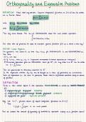
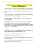
Figure 2.1 shows the LTSpice schematic of the inverting configuration of an Operational
Amplifer with an input resistor (1k ohm) and a feedback resistor (10k ohm).
Figure 2.1: Inverting Amplifier LTSpice Schematic
1
, 1. I will calculate the closed loop voltage gain of the circuit using the equation for
gain of an inverting operational amplifier.
2. I will simulate the circuit in LTSpice and run a Transient Analysis with a
sinusoidal input that has a 0.4 peak-to-peak voltage and a 1kHz frequency. I will
use Vs and Vout obtained from this analysis to calculate the gain of the circuit. I
will also do an AC sweer in order to obtain the frequency response of (Vout/Vin)
in decibals. I will use the frequency response to determine the f3db and the unity
gain frequency.
3. I will build the physical circuit using the Analog Discovery Kit to supply the two
DC voltage supplies (5V and -5V), an AC voltage supply (sinusoidal) with a 0.4
peak-to-peak voltage and 1kHz frequency, a 10kohm resistor, a 1kohm resistor
and an op-amp (OP27). I will use the input and output voltage waveforms (out of
phase) produced by the ADK oscilloscope to determine the gain.
4. I will compare the theoretical results obtained from the LTSpice Transient
Analysis and AC sweep to the experimental values obtained from the physical
circuit, namely the ADK.
2.2 Non-Inverting Amplifer
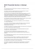
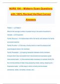
Figure 2.1 shows the LTSpice schematic of the non-inverting configuration of an
Operational Amplifer with an input resistor (1k ohm) and a feedback resistor (10k ohm).
Figure 2.2: Non-Inverting Amplifier LTSpice Schematic.
2
EEE 334
Lab 2 Online: Operational Amplifiers Experiment
2025/26 Update, 100% Guaranteed Pass ||Complete A+
Guide
This Document Contains:
EEE 334
Lab 2 Online: Operational Amplifiers Experiment
100% Guaranteed Pass
Complete A+ Guide
,Introduction:
This lab focuses on different properties and applications of inverting/noninverting and
integrating/differentiating operational amplifiers.
Equipment and Components:
a. Equipment
- Analog Discovery Kit 3, Analog Parts kit, Digital Multimeter, Breadboard.
b. Components
- OP27, 10kohm resistor, 1kohm resistor, and .01 micro-Farad capacitor.
Course of Action:
2.1 Inverting Amplifier
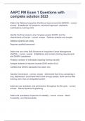
Figure 2.1 shows the LTSpice schematic of the inverting configuration of an Operational
Amplifer with an input resistor (1k ohm) and a feedback resistor (10k ohm).
Figure 2.1: Inverting Amplifier LTSpice Schematic
1
, 1. I will calculate the closed loop voltage gain of the circuit using the equation for
gain of an inverting operational amplifier.
2. I will simulate the circuit in LTSpice and run a Transient Analysis with a
sinusoidal input that has a 0.4 peak-to-peak voltage and a 1kHz frequency. I will
use Vs and Vout obtained from this analysis to calculate the gain of the circuit. I
will also do an AC sweer in order to obtain the frequency response of (Vout/Vin)
in decibals. I will use the frequency response to determine the f3db and the unity
gain frequency.
3. I will build the physical circuit using the Analog Discovery Kit to supply the two
DC voltage supplies (5V and -5V), an AC voltage supply (sinusoidal) with a 0.4
peak-to-peak voltage and 1kHz frequency, a 10kohm resistor, a 1kohm resistor
and an op-amp (OP27). I will use the input and output voltage waveforms (out of
phase) produced by the ADK oscilloscope to determine the gain.
4. I will compare the theoretical results obtained from the LTSpice Transient
Analysis and AC sweep to the experimental values obtained from the physical
circuit, namely the ADK.
2.2 Non-Inverting Amplifer
Figure 2.1 shows the LTSpice schematic of the non-inverting configuration of an
Operational Amplifer with an input resistor (1k ohm) and a feedback resistor (10k ohm).
Figure 2.2: Non-Inverting Amplifier LTSpice Schematic.
2