5XCA0 - Fundamentals of Electronics
A Summary
Fe Fan Li
October 20, 2020
, Contents
Preface 3
1 Basic Electrical Circuits and Components 5
1.1 Electrical circuits . . . . . . . . . . . . . . . . . . . . . . . . . . . . . . . . . . . . . . . . . 5
1.2 Direct current and alternating current . . . . . . . . . . . . . . . . . . . . . . . . . . . . . 5
1.3 Resistors, capacitors and inductors . . . . . . . . . . . . . . . . . . . . . . . . . . . . . . . 6
1.4 Ohm’s law . . . . . . . . . . . . . . . . . . . . . . . . . . . . . . . . . . . . . . . . . . . . . 6
1.5 Kirchhoff’s laws . . . . . . . . . . . . . . . . . . . . . . . . . . . . . . . . . . . . . . . . . . 7
1.6 Power dissipation in resistors . . . . . . . . . . . . . . . . . . . . . . . . . . . . . . . . . . 7
1.7 Resistors in series . . . . . . . . . . . . . . . . . . . . . . . . . . . . . . . . . . . . . . . . . 8
1.8 Resistance in parallel . . . . . . . . . . . . . . . . . . . . . . . . . . . . . . . . . . . . . . . 8
1.9 Resistive potential dividers . . . . . . . . . . . . . . . . . . . . . . . . . . . . . . . . . . . 8
1.10 Sinusoidal quantities . . . . . . . . . . . . . . . . . . . . . . . . . . . . . . . . . . . . . . . 8
1.11 Circuit symbols . . . . . . . . . . . . . . . . . . . . . . . . . . . . . . . . . . . . . . . . . . 8
2 Measurement of Voltages and Currents 10
2.1 Introduction . . . . . . . . . . . . . . . . . . . . . . . . . . . . . . . . . . . . . . . . . . . . 10
2.2 Sine waves . . . . . . . . . . . . . . . . . . . . . . . . . . . . . . . . . . . . . . . . . . . . . 10
2.3 Square waves . . . . . . . . . . . . . . . . . . . . . . . . . . . . . . . . . . . . . . . . . . . 12
2.4 Measuring voltages and currents . . . . . . . . . . . . . . . . . . . . . . . . . . . . . . . . 12
2.5 Digital multimeters . . . . . . . . . . . . . . . . . . . . . . . . . . . . . . . . . . . . . . . . 12
2.6 Oscilloscopes . . . . . . . . . . . . . . . . . . . . . . . . . . . . . . . . . . . . . . . . . . . 12
3 Resistance and DC circuits 13
3.1 Current and charge . . . . . . . . . . . . . . . . . . . . . . . . . . . . . . . . . . . . . . . . 13
3.2 Voltage sources . . . . . . . . . . . . . . . . . . . . . . . . . . . . . . . . . . . . . . . . . . 13
3.3 Current sources . . . . . . . . . . . . . . . . . . . . . . . . . . . . . . . . . . . . . . . . . . 14
3.4 Resistance and Ohm’s law . . . . . . . . . . . . . . . . . . . . . . . . . . . . . . . . . . . . 14
3.5 Resistors in series and parallel . . . . . . . . . . . . . . . . . . . . . . . . . . . . . . . . . . 14
3.6 Kirchhoff’s laws . . . . . . . . . . . . . . . . . . . . . . . . . . . . . . . . . . . . . . . . . . 14
3.7 Thevenin’s theorem and Norton’s theorem . . . . . . . . . . . . . . . . . . . . . . . . . . . 15
3.8 Nodal analysis . . . . . . . . . . . . . . . . . . . . . . . . . . . . . . . . . . . . . . . . . . 16
3.9 Solving simultaneous circuit equations . . . . . . . . . . . . . . . . . . . . . . . . . . . . . 16
4 Capacitance and Electric Fields 17
4.1 Capacitors and capacitance . . . . . . . . . . . . . . . . . . . . . . . . . . . . . . . . . . . 17
4.2 The effect of a capacitor’s dimensions on its capacitance . . . . . . . . . . . . . . . . . . . 17
4.3 Electric field strength and electric flux density . . . . . . . . . . . . . . . . . . . . . . . . . 17
4.4 Capacitors in series and parallel . . . . . . . . . . . . . . . . . . . . . . . . . . . . . . . . . 17
4.5 Relationship between voltage and current in a capacitor . . . . . . . . . . . . . . . . . . . 18
4.6 Sinusoidal voltages and currents . . . . . . . . . . . . . . . . . . . . . . . . . . . . . . . . . 18
4.7 Energy stored in a charged capacitor . . . . . . . . . . . . . . . . . . . . . . . . . . . . . . 18
4.8 Circuit symbols . . . . . . . . . . . . . . . . . . . . . . . . . . . . . . . . . . . . . . . . . . 19
5 Inductance and Magnetic Fields 20
5.1 Electromagnetism . . . . . . . . . . . . . . . . . . . . . . . . . . . . . . . . . . . . . . . . . 20
5.2 Inductance . . . . . . . . . . . . . . . . . . . . . . . . . . . . . . . . . . . . . . . . . . . . 20
5.3 Self-inductance . . . . . . . . . . . . . . . . . . . . . . . . . . . . . . . . . . . . . . . . . . 21
1
, 5.4 Inductance . . . . . . . . . . . . . . . . . . . . . . . . . . . . . . . . . . . . . . . . . . . . 21
5.5 Inductors in series and parallel . . . . . . . . . . . . . . . . . . . . . . . . . . . . . . . . . 21
5.6 Relationship between voltage and current in an inductor . . . . . . . . . . . . . . . . . . . 21
5.7 Sinusoidal voltages and currents . . . . . . . . . . . . . . . . . . . . . . . . . . . . . . . . . 21
5.8 Energy stored in an inductor . . . . . . . . . . . . . . . . . . . . . . . . . . . . . . . . . . 21
5.9 The use of inductance in sensors . . . . . . . . . . . . . . . . . . . . . . . . . . . . . . . . 22
6 Alternating Voltages and Currents 23
6.1 Relationship between voltage and current . . . . . . . . . . . . . . . . . . . . . . . . . . . 23
6.2 Complex notation . . . . . . . . . . . . . . . . . . . . . . . . . . . . . . . . . . . . . . . . . 23
7 Frequency Characteristics of AC circuits 26
7.1 Two-port networks . . . . . . . . . . . . . . . . . . . . . . . . . . . . . . . . . . . . . . . . 26
7.2 The decibel (dB) . . . . . . . . . . . . . . . . . . . . . . . . . . . . . . . . . . . . . . . . . 26
7.3 Frequency response . . . . . . . . . . . . . . . . . . . . . . . . . . . . . . . . . . . . . . . . 26
7.4 A high-pass RC network . . . . . . . . . . . . . . . . . . . . . . . . . . . . . . . . . . . . . 27
7.5 A low-pass RC network . . . . . . . . . . . . . . . . . . . . . . . . . . . . . . . . . . . . . 27
7.6 A low-pass RL network . . . . . . . . . . . . . . . . . . . . . . . . . . . . . . . . . . . . . 28
7.7 A high-pass RL network . . . . . . . . . . . . . . . . . . . . . . . . . . . . . . . . . . . . . 28
7.8 A comparison of RC and LC networks . . . . . . . . . . . . . . . . . . . . . . . . . . . . . 29
7.9 Bode diagrams . . . . . . . . . . . . . . . . . . . . . . . . . . . . . . . . . . . . . . . . . . 29
7.10 Combining effects of several stages . . . . . . . . . . . . . . . . . . . . . . . . . . . . . . . 29
8 Electronic Systems 32
8.1 Systems . . . . . . . . . . . . . . . . . . . . . . . . . . . . . . . . . . . . . . . . . . . . . . 32
8.2 System inputs and outputs . . . . . . . . . . . . . . . . . . . . . . . . . . . . . . . . . . . 32
8.3 Physical quantities and electrical signals . . . . . . . . . . . . . . . . . . . . . . . . . . . . 32
8.4 System block diagrams . . . . . . . . . . . . . . . . . . . . . . . . . . . . . . . . . . . . . . 32
9 Sensors 34
9.1 Introduction . . . . . . . . . . . . . . . . . . . . . . . . . . . . . . . . . . . . . . . . . . . . 34
9.2 Describing sensor performance . . . . . . . . . . . . . . . . . . . . . . . . . . . . . . . . . 34
10 Actuators 35
11 Amplification 36
11.1 Electronic Amplifiers . . . . . . . . . . . . . . . . . . . . . . . . . . . . . . . . . . . . . . . 36
11.2 Sources and loads . . . . . . . . . . . . . . . . . . . . . . . . . . . . . . . . . . . . . . . . . 36
11.3 Equivalent circuit of an amplifier . . . . . . . . . . . . . . . . . . . . . . . . . . . . . . . . 36
11.4 Output power . . . . . . . . . . . . . . . . . . . . . . . . . . . . . . . . . . . . . . . . . . . 36
11.5 Power gain . . . . . . . . . . . . . . . . . . . . . . . . . . . . . . . . . . . . . . . . . . . . 37
11.6 Frequency response and bandwidth . . . . . . . . . . . . . . . . . . . . . . . . . . . . . . . 37
11.7 Differential amplifiers . . . . . . . . . . . . . . . . . . . . . . . . . . . . . . . . . . . . . . 37
12 Control and Feedback 38
12.1 Open-loop and closed-loop systems . . . . . . . . . . . . . . . . . . . . . . . . . . . . . . . 38
12.2 Automatic control systems . . . . . . . . . . . . . . . . . . . . . . . . . . . . . . . . . . . . 38
12.3 Feedback systems . . . . . . . . . . . . . . . . . . . . . . . . . . . . . . . . . . . . . . . . . 38
12.4 Negative feedback . . . . . . . . . . . . . . . . . . . . . . . . . . . . . . . . . . . . . . . . 39
12.5 The effects of negative feedback . . . . . . . . . . . . . . . . . . . . . . . . . . . . . . . . . 39
13 Operational Amplifiers 40
13.1 An ideal operational amplifier . . . . . . . . . . . . . . . . . . . . . . . . . . . . . . . . . . 40
13.2 Some basic operational amplifier circuits . . . . . . . . . . . . . . . . . . . . . . . . . . . . 40
13.3 Some other useful circuits . . . . . . . . . . . . . . . . . . . . . . . . . . . . . . . . . . . . 41
13.4 Real operational amplifiers . . . . . . . . . . . . . . . . . . . . . . . . . . . . . . . . . . . 44
13.5 Selecting component values for op-amp circuits . . . . . . . . . . . . . . . . . . . . . . . . 44
13.6 The effects of feedback on op-amp circuits . . . . . . . . . . . . . . . . . . . . . . . . . . . 44
14 Semiconductors and Diodes 46
2
, 14.1 Electrical properties of solids . . . . . . . . . . . . . . . . . . . . . . . . . . . . . . . . . . 46
14.2 Semiconductors . . . . . . . . . . . . . . . . . . . . . . . . . . . . . . . . . . . . . . . . . . 46
14.3 pn junction . . . . . . . . . . . . . . . . . . . . . . . . . . . . . . . . . . . . . . . . . . . . 46
14.4 Diodes . . . . . . . . . . . . . . . . . . . . . . . . . . . . . . . . . . . . . . . . . . . . . . . 47
14.5 Semiconductor diodes . . . . . . . . . . . . . . . . . . . . . . . . . . . . . . . . . . . . . . 47
14.6 Diode circuits . . . . . . . . . . . . . . . . . . . . . . . . . . . . . . . . . . . . . . . . . . . 47
15 Field-effect Transistors 48
15.1 An overview of field-effect transistors . . . . . . . . . . . . . . . . . . . . . . . . . . . . . . 48
15.2 Insulated-gate Field-effect Transistors . . . . . . . . . . . . . . . . . . . . . . . . . . . . . 48
15.3 FET characteristics . . . . . . . . . . . . . . . . . . . . . . . . . . . . . . . . . . . . . . . . 49
15.4 FET amplifiers . . . . . . . . . . . . . . . . . . . . . . . . . . . . . . . . . . . . . . . . . . 49
16 Digital Systems 53
16.1 Binary quantities and variables . . . . . . . . . . . . . . . . . . . . . . . . . . . . . . . . . 53
16.2 Logic gates . . . . . . . . . . . . . . . . . . . . . . . . . . . . . . . . . . . . . . . . . . . . 53
16.3 Boolean algebra . . . . . . . . . . . . . . . . . . . . . . . . . . . . . . . . . . . . . . . . . . 53
16.4 Combinational logic . . . . . . . . . . . . . . . . . . . . . . . . . . . . . . . . . . . . . . . 53
16.5 Boolean algebraic manipulation . . . . . . . . . . . . . . . . . . . . . . . . . . . . . . . . . 53
16.6 Algebraic simplification . . . . . . . . . . . . . . . . . . . . . . . . . . . . . . . . . . . . . 53
16.7 Karnaugh maps . . . . . . . . . . . . . . . . . . . . . . . . . . . . . . . . . . . . . . . . . . 53
16.8 Propagation delay and hazards . . . . . . . . . . . . . . . . . . . . . . . . . . . . . . . . . 54
16.9 Number systems and binary arhithmetic . . . . . . . . . . . . . . . . . . . . . . . . . . . . 54
16.10Numeric and alphabetic codes . . . . . . . . . . . . . . . . . . . . . . . . . . . . . . . . . . 54
17 Sequential Logic 57
17.1 Bistables . . . . . . . . . . . . . . . . . . . . . . . . . . . . . . . . . . . . . . . . . . . . . . 57
17.2 Memory registers . . . . . . . . . . . . . . . . . . . . . . . . . . . . . . . . . . . . . . . . . 58
17.3 Shift registers . . . . . . . . . . . . . . . . . . . . . . . . . . . . . . . . . . . . . . . . . . . 59
17.4 Counters . . . . . . . . . . . . . . . . . . . . . . . . . . . . . . . . . . . . . . . . . . . . . . 59
18 Data acquisition and conversion 62
3
,Preface
This summary contains an overview of the contents of the lecture slides for the course and the accompa-
nying book Electronics: A Systems Approach. There will also be some examples from old final exams.
This is based on the course taught in the year 2018-2019. Use this summary at your own risk; I am
not responsible for your exam and sections in this summary may contain errors, redundant
information or absence of important information. My recommendation is that you also
study the book, lecture slides and exercises as well as exam questions thoroughly.
When I took the course, some chapter will get treated during the lectures but are not really part of the
exams. The chapters I think you should study if you only care about the exams are:
• Basic Electrical Circuits and Components;
• Resistance and DC circuits;
• Capacitance and Electric Fields;
• Inductance and Magnetic Fields;
• Alternating Voltages and Currents;
• Frequency Characteristics of AC Circuits;
• Operational Amplifiers;
• Field-effect Transistors;
• Digital Systems;
• Sequential Logic.
Again, I want to stress that I do not know if the content of the course has changed. I also have a version
without the ’unnecessary parts and Exam examples’.
4
,Chapter 1
Basic Electrical Circuits and
Components
I assume you know the units and common unit prefixes. Otherwise, look them up.
1.1 Electrical circuits
Electric charge
Electric charges experience a force when in an external electric field, and can be positively or negatively
charged. Electrons have 1 negative quantum of charge.
Electric current
An electric current is a flow of electric charge, often a flow of electrons. Conventional current is defined
as a flow of electricity from a positive to a negative region.
Current flow in a circuit
A sustained circuit requires a complete circuit for the recirculation of electrons. It also requires some
stimulus to cause the electrons to flow around this circuit.
Electromotive force and potential difference
The stimulus that causes an electric current to flow is an electromotive force or e.m.f. The e.m.f.
represents the energy introduced into the circuit by a source such as a battery or a generator. The
energy transferred from the the source to the load results in a change in the electrical potential at each
point in the load. Between any two points in the load there will exist a certain potential difference. Both
e.m.f. and potential difference are measured in volts.
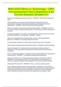
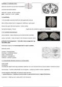
Voltage reference points
All potentials within circuits must be measured with respect to some reference point. Often voltages are
measured with respect to a zero volt reference called the ground or earth. See Figure 1,
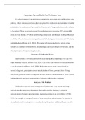
Representing voltages in circuit diagrams
Convention is to use an arrow, which is taken to represent the voltage on the head with respect to the
tail. Sometimes a + and − signs are being used. Labels represent voltages with respect to earth. See
Figure 2,
1.2 Direct current and alternating current
Currents in electrical circuits may be constant or may vary with time. When currents vary with time
they may be unidirectional or alternating. When the current flowing in a conductor always flows in the
same direction this is direct current (DC). When the direction of the current (periodically changes) this
is alternating current (AC). A varying current can be considered as the sum of a DC and an AC current.
5
, Figure 1: Indicating voltage reference points.
Figure 2: Indicating voltages in circuit diagrams.
1.3 Resistors, capacitors and inductors
Resistors
Resistors are components whose main characteristic is that they provide resistance between their two
electrical terminals. The resistance of a circuit represents its opposition to the flow of electric current.
The resistance of a circuit represents its opposition to the flow of electric current. The resistance is
measured in Ohms Ω.
Capacitors
Capacitors are components whose main characteristic is that they exhibit capacitance between their
two terminals. Energy is stored in an electric field that is created between the two conductors. The
capacitance is measured in Farad F
Inductors
Inductors are components whose main characteristic is that they exhibit inductance in between their two
terminals. Energy is stored in a magnetic field. The inductance is measured in H.
1.4 Ohm’s law
Ohm’s law states that the current I flowing in a conductor is directly proportional to the applied voltage
V . and inversely proportional to its resistance R. The relationships between the voltage, current and
resistance are given by equation (1),
V = IR
V
I= (1)
R
V
R=
I
6
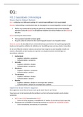
, 1.5 Kirchhoff ’s laws
Current law
At any instant the algebraic sum of the currents flowing into any junction (or node) in a circuit is zero.
The volage law is described by equation (2),
I=0 (2)
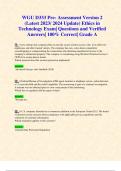
For an example see Figure 3.
I1 − I2 − I3 = 0
I2 = I1 − I3 = 10 − 3 = 7 A
Figure 3: Example for Kirchhoff’s current law.
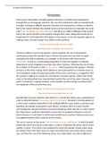
Voltage law
At any instant, the algebraic sum of all the voltages arouund any loop in a circuit is zero, given by
equation (3),
V =0 (3)
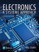
See for an example Figure 4.
E − V1 − V2 = 0
V1 = E − V2 = 12 − 7 = 5 V.
Figure 4: Example of Kirchhoff’s voltage law.
1.6 Power dissipation in resistors
The instantaneous power dissipation P of a resistor is given by equation (4),
P =VI
P = I 2R (4)
V2
P =
R
7
A Summary
Fe Fan Li
October 20, 2020
, Contents
Preface 3
1 Basic Electrical Circuits and Components 5
1.1 Electrical circuits . . . . . . . . . . . . . . . . . . . . . . . . . . . . . . . . . . . . . . . . . 5
1.2 Direct current and alternating current . . . . . . . . . . . . . . . . . . . . . . . . . . . . . 5
1.3 Resistors, capacitors and inductors . . . . . . . . . . . . . . . . . . . . . . . . . . . . . . . 6
1.4 Ohm’s law . . . . . . . . . . . . . . . . . . . . . . . . . . . . . . . . . . . . . . . . . . . . . 6
1.5 Kirchhoff’s laws . . . . . . . . . . . . . . . . . . . . . . . . . . . . . . . . . . . . . . . . . . 7
1.6 Power dissipation in resistors . . . . . . . . . . . . . . . . . . . . . . . . . . . . . . . . . . 7
1.7 Resistors in series . . . . . . . . . . . . . . . . . . . . . . . . . . . . . . . . . . . . . . . . . 8
1.8 Resistance in parallel . . . . . . . . . . . . . . . . . . . . . . . . . . . . . . . . . . . . . . . 8
1.9 Resistive potential dividers . . . . . . . . . . . . . . . . . . . . . . . . . . . . . . . . . . . 8
1.10 Sinusoidal quantities . . . . . . . . . . . . . . . . . . . . . . . . . . . . . . . . . . . . . . . 8
1.11 Circuit symbols . . . . . . . . . . . . . . . . . . . . . . . . . . . . . . . . . . . . . . . . . . 8
2 Measurement of Voltages and Currents 10
2.1 Introduction . . . . . . . . . . . . . . . . . . . . . . . . . . . . . . . . . . . . . . . . . . . . 10
2.2 Sine waves . . . . . . . . . . . . . . . . . . . . . . . . . . . . . . . . . . . . . . . . . . . . . 10
2.3 Square waves . . . . . . . . . . . . . . . . . . . . . . . . . . . . . . . . . . . . . . . . . . . 12
2.4 Measuring voltages and currents . . . . . . . . . . . . . . . . . . . . . . . . . . . . . . . . 12
2.5 Digital multimeters . . . . . . . . . . . . . . . . . . . . . . . . . . . . . . . . . . . . . . . . 12
2.6 Oscilloscopes . . . . . . . . . . . . . . . . . . . . . . . . . . . . . . . . . . . . . . . . . . . 12
3 Resistance and DC circuits 13
3.1 Current and charge . . . . . . . . . . . . . . . . . . . . . . . . . . . . . . . . . . . . . . . . 13
3.2 Voltage sources . . . . . . . . . . . . . . . . . . . . . . . . . . . . . . . . . . . . . . . . . . 13
3.3 Current sources . . . . . . . . . . . . . . . . . . . . . . . . . . . . . . . . . . . . . . . . . . 14
3.4 Resistance and Ohm’s law . . . . . . . . . . . . . . . . . . . . . . . . . . . . . . . . . . . . 14
3.5 Resistors in series and parallel . . . . . . . . . . . . . . . . . . . . . . . . . . . . . . . . . . 14
3.6 Kirchhoff’s laws . . . . . . . . . . . . . . . . . . . . . . . . . . . . . . . . . . . . . . . . . . 14
3.7 Thevenin’s theorem and Norton’s theorem . . . . . . . . . . . . . . . . . . . . . . . . . . . 15
3.8 Nodal analysis . . . . . . . . . . . . . . . . . . . . . . . . . . . . . . . . . . . . . . . . . . 16
3.9 Solving simultaneous circuit equations . . . . . . . . . . . . . . . . . . . . . . . . . . . . . 16
4 Capacitance and Electric Fields 17
4.1 Capacitors and capacitance . . . . . . . . . . . . . . . . . . . . . . . . . . . . . . . . . . . 17
4.2 The effect of a capacitor’s dimensions on its capacitance . . . . . . . . . . . . . . . . . . . 17
4.3 Electric field strength and electric flux density . . . . . . . . . . . . . . . . . . . . . . . . . 17
4.4 Capacitors in series and parallel . . . . . . . . . . . . . . . . . . . . . . . . . . . . . . . . . 17
4.5 Relationship between voltage and current in a capacitor . . . . . . . . . . . . . . . . . . . 18
4.6 Sinusoidal voltages and currents . . . . . . . . . . . . . . . . . . . . . . . . . . . . . . . . . 18
4.7 Energy stored in a charged capacitor . . . . . . . . . . . . . . . . . . . . . . . . . . . . . . 18
4.8 Circuit symbols . . . . . . . . . . . . . . . . . . . . . . . . . . . . . . . . . . . . . . . . . . 19
5 Inductance and Magnetic Fields 20
5.1 Electromagnetism . . . . . . . . . . . . . . . . . . . . . . . . . . . . . . . . . . . . . . . . . 20
5.2 Inductance . . . . . . . . . . . . . . . . . . . . . . . . . . . . . . . . . . . . . . . . . . . . 20
5.3 Self-inductance . . . . . . . . . . . . . . . . . . . . . . . . . . . . . . . . . . . . . . . . . . 21
1
, 5.4 Inductance . . . . . . . . . . . . . . . . . . . . . . . . . . . . . . . . . . . . . . . . . . . . 21
5.5 Inductors in series and parallel . . . . . . . . . . . . . . . . . . . . . . . . . . . . . . . . . 21
5.6 Relationship between voltage and current in an inductor . . . . . . . . . . . . . . . . . . . 21
5.7 Sinusoidal voltages and currents . . . . . . . . . . . . . . . . . . . . . . . . . . . . . . . . . 21
5.8 Energy stored in an inductor . . . . . . . . . . . . . . . . . . . . . . . . . . . . . . . . . . 21
5.9 The use of inductance in sensors . . . . . . . . . . . . . . . . . . . . . . . . . . . . . . . . 22
6 Alternating Voltages and Currents 23
6.1 Relationship between voltage and current . . . . . . . . . . . . . . . . . . . . . . . . . . . 23
6.2 Complex notation . . . . . . . . . . . . . . . . . . . . . . . . . . . . . . . . . . . . . . . . . 23
7 Frequency Characteristics of AC circuits 26
7.1 Two-port networks . . . . . . . . . . . . . . . . . . . . . . . . . . . . . . . . . . . . . . . . 26
7.2 The decibel (dB) . . . . . . . . . . . . . . . . . . . . . . . . . . . . . . . . . . . . . . . . . 26
7.3 Frequency response . . . . . . . . . . . . . . . . . . . . . . . . . . . . . . . . . . . . . . . . 26
7.4 A high-pass RC network . . . . . . . . . . . . . . . . . . . . . . . . . . . . . . . . . . . . . 27
7.5 A low-pass RC network . . . . . . . . . . . . . . . . . . . . . . . . . . . . . . . . . . . . . 27
7.6 A low-pass RL network . . . . . . . . . . . . . . . . . . . . . . . . . . . . . . . . . . . . . 28
7.7 A high-pass RL network . . . . . . . . . . . . . . . . . . . . . . . . . . . . . . . . . . . . . 28
7.8 A comparison of RC and LC networks . . . . . . . . . . . . . . . . . . . . . . . . . . . . . 29
7.9 Bode diagrams . . . . . . . . . . . . . . . . . . . . . . . . . . . . . . . . . . . . . . . . . . 29
7.10 Combining effects of several stages . . . . . . . . . . . . . . . . . . . . . . . . . . . . . . . 29
8 Electronic Systems 32
8.1 Systems . . . . . . . . . . . . . . . . . . . . . . . . . . . . . . . . . . . . . . . . . . . . . . 32
8.2 System inputs and outputs . . . . . . . . . . . . . . . . . . . . . . . . . . . . . . . . . . . 32
8.3 Physical quantities and electrical signals . . . . . . . . . . . . . . . . . . . . . . . . . . . . 32
8.4 System block diagrams . . . . . . . . . . . . . . . . . . . . . . . . . . . . . . . . . . . . . . 32
9 Sensors 34
9.1 Introduction . . . . . . . . . . . . . . . . . . . . . . . . . . . . . . . . . . . . . . . . . . . . 34
9.2 Describing sensor performance . . . . . . . . . . . . . . . . . . . . . . . . . . . . . . . . . 34
10 Actuators 35
11 Amplification 36
11.1 Electronic Amplifiers . . . . . . . . . . . . . . . . . . . . . . . . . . . . . . . . . . . . . . . 36
11.2 Sources and loads . . . . . . . . . . . . . . . . . . . . . . . . . . . . . . . . . . . . . . . . . 36
11.3 Equivalent circuit of an amplifier . . . . . . . . . . . . . . . . . . . . . . . . . . . . . . . . 36
11.4 Output power . . . . . . . . . . . . . . . . . . . . . . . . . . . . . . . . . . . . . . . . . . . 36
11.5 Power gain . . . . . . . . . . . . . . . . . . . . . . . . . . . . . . . . . . . . . . . . . . . . 37
11.6 Frequency response and bandwidth . . . . . . . . . . . . . . . . . . . . . . . . . . . . . . . 37
11.7 Differential amplifiers . . . . . . . . . . . . . . . . . . . . . . . . . . . . . . . . . . . . . . 37
12 Control and Feedback 38
12.1 Open-loop and closed-loop systems . . . . . . . . . . . . . . . . . . . . . . . . . . . . . . . 38
12.2 Automatic control systems . . . . . . . . . . . . . . . . . . . . . . . . . . . . . . . . . . . . 38
12.3 Feedback systems . . . . . . . . . . . . . . . . . . . . . . . . . . . . . . . . . . . . . . . . . 38
12.4 Negative feedback . . . . . . . . . . . . . . . . . . . . . . . . . . . . . . . . . . . . . . . . 39
12.5 The effects of negative feedback . . . . . . . . . . . . . . . . . . . . . . . . . . . . . . . . . 39
13 Operational Amplifiers 40
13.1 An ideal operational amplifier . . . . . . . . . . . . . . . . . . . . . . . . . . . . . . . . . . 40
13.2 Some basic operational amplifier circuits . . . . . . . . . . . . . . . . . . . . . . . . . . . . 40
13.3 Some other useful circuits . . . . . . . . . . . . . . . . . . . . . . . . . . . . . . . . . . . . 41
13.4 Real operational amplifiers . . . . . . . . . . . . . . . . . . . . . . . . . . . . . . . . . . . 44
13.5 Selecting component values for op-amp circuits . . . . . . . . . . . . . . . . . . . . . . . . 44
13.6 The effects of feedback on op-amp circuits . . . . . . . . . . . . . . . . . . . . . . . . . . . 44
14 Semiconductors and Diodes 46
2
, 14.1 Electrical properties of solids . . . . . . . . . . . . . . . . . . . . . . . . . . . . . . . . . . 46
14.2 Semiconductors . . . . . . . . . . . . . . . . . . . . . . . . . . . . . . . . . . . . . . . . . . 46
14.3 pn junction . . . . . . . . . . . . . . . . . . . . . . . . . . . . . . . . . . . . . . . . . . . . 46
14.4 Diodes . . . . . . . . . . . . . . . . . . . . . . . . . . . . . . . . . . . . . . . . . . . . . . . 47
14.5 Semiconductor diodes . . . . . . . . . . . . . . . . . . . . . . . . . . . . . . . . . . . . . . 47
14.6 Diode circuits . . . . . . . . . . . . . . . . . . . . . . . . . . . . . . . . . . . . . . . . . . . 47
15 Field-effect Transistors 48
15.1 An overview of field-effect transistors . . . . . . . . . . . . . . . . . . . . . . . . . . . . . . 48
15.2 Insulated-gate Field-effect Transistors . . . . . . . . . . . . . . . . . . . . . . . . . . . . . 48
15.3 FET characteristics . . . . . . . . . . . . . . . . . . . . . . . . . . . . . . . . . . . . . . . . 49
15.4 FET amplifiers . . . . . . . . . . . . . . . . . . . . . . . . . . . . . . . . . . . . . . . . . . 49
16 Digital Systems 53
16.1 Binary quantities and variables . . . . . . . . . . . . . . . . . . . . . . . . . . . . . . . . . 53
16.2 Logic gates . . . . . . . . . . . . . . . . . . . . . . . . . . . . . . . . . . . . . . . . . . . . 53
16.3 Boolean algebra . . . . . . . . . . . . . . . . . . . . . . . . . . . . . . . . . . . . . . . . . . 53
16.4 Combinational logic . . . . . . . . . . . . . . . . . . . . . . . . . . . . . . . . . . . . . . . 53
16.5 Boolean algebraic manipulation . . . . . . . . . . . . . . . . . . . . . . . . . . . . . . . . . 53
16.6 Algebraic simplification . . . . . . . . . . . . . . . . . . . . . . . . . . . . . . . . . . . . . 53
16.7 Karnaugh maps . . . . . . . . . . . . . . . . . . . . . . . . . . . . . . . . . . . . . . . . . . 53
16.8 Propagation delay and hazards . . . . . . . . . . . . . . . . . . . . . . . . . . . . . . . . . 54
16.9 Number systems and binary arhithmetic . . . . . . . . . . . . . . . . . . . . . . . . . . . . 54
16.10Numeric and alphabetic codes . . . . . . . . . . . . . . . . . . . . . . . . . . . . . . . . . . 54
17 Sequential Logic 57
17.1 Bistables . . . . . . . . . . . . . . . . . . . . . . . . . . . . . . . . . . . . . . . . . . . . . . 57
17.2 Memory registers . . . . . . . . . . . . . . . . . . . . . . . . . . . . . . . . . . . . . . . . . 58
17.3 Shift registers . . . . . . . . . . . . . . . . . . . . . . . . . . . . . . . . . . . . . . . . . . . 59
17.4 Counters . . . . . . . . . . . . . . . . . . . . . . . . . . . . . . . . . . . . . . . . . . . . . . 59
18 Data acquisition and conversion 62
3
,Preface
This summary contains an overview of the contents of the lecture slides for the course and the accompa-
nying book Electronics: A Systems Approach. There will also be some examples from old final exams.
This is based on the course taught in the year 2018-2019. Use this summary at your own risk; I am
not responsible for your exam and sections in this summary may contain errors, redundant
information or absence of important information. My recommendation is that you also
study the book, lecture slides and exercises as well as exam questions thoroughly.
When I took the course, some chapter will get treated during the lectures but are not really part of the
exams. The chapters I think you should study if you only care about the exams are:
• Basic Electrical Circuits and Components;
• Resistance and DC circuits;
• Capacitance and Electric Fields;
• Inductance and Magnetic Fields;
• Alternating Voltages and Currents;
• Frequency Characteristics of AC Circuits;
• Operational Amplifiers;
• Field-effect Transistors;
• Digital Systems;
• Sequential Logic.
Again, I want to stress that I do not know if the content of the course has changed. I also have a version
without the ’unnecessary parts and Exam examples’.
4
,Chapter 1
Basic Electrical Circuits and
Components
I assume you know the units and common unit prefixes. Otherwise, look them up.
1.1 Electrical circuits
Electric charge
Electric charges experience a force when in an external electric field, and can be positively or negatively
charged. Electrons have 1 negative quantum of charge.
Electric current
An electric current is a flow of electric charge, often a flow of electrons. Conventional current is defined
as a flow of electricity from a positive to a negative region.
Current flow in a circuit
A sustained circuit requires a complete circuit for the recirculation of electrons. It also requires some
stimulus to cause the electrons to flow around this circuit.
Electromotive force and potential difference
The stimulus that causes an electric current to flow is an electromotive force or e.m.f. The e.m.f.
represents the energy introduced into the circuit by a source such as a battery or a generator. The
energy transferred from the the source to the load results in a change in the electrical potential at each
point in the load. Between any two points in the load there will exist a certain potential difference. Both
e.m.f. and potential difference are measured in volts.
Voltage reference points
All potentials within circuits must be measured with respect to some reference point. Often voltages are
measured with respect to a zero volt reference called the ground or earth. See Figure 1,
Representing voltages in circuit diagrams
Convention is to use an arrow, which is taken to represent the voltage on the head with respect to the
tail. Sometimes a + and − signs are being used. Labels represent voltages with respect to earth. See
Figure 2,
1.2 Direct current and alternating current
Currents in electrical circuits may be constant or may vary with time. When currents vary with time
they may be unidirectional or alternating. When the current flowing in a conductor always flows in the
same direction this is direct current (DC). When the direction of the current (periodically changes) this
is alternating current (AC). A varying current can be considered as the sum of a DC and an AC current.
5
, Figure 1: Indicating voltage reference points.
Figure 2: Indicating voltages in circuit diagrams.
1.3 Resistors, capacitors and inductors
Resistors
Resistors are components whose main characteristic is that they provide resistance between their two
electrical terminals. The resistance of a circuit represents its opposition to the flow of electric current.
The resistance of a circuit represents its opposition to the flow of electric current. The resistance is
measured in Ohms Ω.
Capacitors
Capacitors are components whose main characteristic is that they exhibit capacitance between their
two terminals. Energy is stored in an electric field that is created between the two conductors. The
capacitance is measured in Farad F
Inductors
Inductors are components whose main characteristic is that they exhibit inductance in between their two
terminals. Energy is stored in a magnetic field. The inductance is measured in H.
1.4 Ohm’s law
Ohm’s law states that the current I flowing in a conductor is directly proportional to the applied voltage
V . and inversely proportional to its resistance R. The relationships between the voltage, current and
resistance are given by equation (1),
V = IR
V
I= (1)
R
V
R=
I
6
, 1.5 Kirchhoff ’s laws
Current law
At any instant the algebraic sum of the currents flowing into any junction (or node) in a circuit is zero.
The volage law is described by equation (2),
I=0 (2)
For an example see Figure 3.
I1 − I2 − I3 = 0
I2 = I1 − I3 = 10 − 3 = 7 A
Figure 3: Example for Kirchhoff’s current law.
Voltage law
At any instant, the algebraic sum of all the voltages arouund any loop in a circuit is zero, given by
equation (3),
V =0 (3)
See for an example Figure 4.
E − V1 − V2 = 0
V1 = E − V2 = 12 − 7 = 5 V.
Figure 4: Example of Kirchhoff’s voltage law.
1.6 Power dissipation in resistors
The instantaneous power dissipation P of a resistor is given by equation (4),
P =VI
P = I 2R (4)
V2
P =
R
7