Lab 2: Multiplexers, Decoders, and
the Arithmetic Logic Unit (ALU)
Prerequisites: Before beginning this lab, you must:
Understand how to use the tool flow (See the installation guide and Lab 0)
Understand the operation of mulitplexers and decoders
Understand 1’s complement and 2’s complement
Have the components available from Lab 1
Equipment: Personal computer with the required software installed.
Files to copy from Lab 1: (all the .dig files)
half_adder.dig
incrementer.dig
full_adder.dig
four_bit_adder.dig
Files to download:
four_bit_mux_top.v
four_bit_mux_stim.txt
alu_top.v
alu_add.v
Objectives: When you have completed this lab, you will be able to:
Build, simulate, and debug a 2-to-1 multiplexer circuit.
Build, simulate, and debug a 4-bit, 2-to-1 multiplexer circuit.
• Use seven-segment displays.
• Build, test, and debug an elementary arithmetic and logic unit (ALU).
• Describe the arithmetic and logical operations of which the ALU is capable.
• Describe the input control line values that correspond to each operation of the ALU.
• Generate tests to verify the operation of the ALU in simulation.
Introduction
In this lab you will continue constructing modules that will be used in assembling the
microprocessor. Our concern in this lab is with circuits that control the flow of data through our
system. You will use the data-flow-control circuit you create in this lab, a 4-bit 2-to-1
multiplexer, to make the microprocessor capable of routing data to appropriate locations. You
will also use seven-segment displays. This will enable you to display numeric values in an easy-
to-read format, which is much nicer than looking at binary values.
In Lab 1 you built combinational logic circuits of increasing complexity. In this laboratory we will
build upon these modules and combine them to form a more complex combinational logic
circuit: the arithmetic logic unit (ALU). The ALU in a microprocessor is the unit that performs all
Version 1.1 Spring 2024 1
,of the arithmetic operations (such as add, subtract, negate, etc.) and all of the logical
operations (such as 1’s complement, AND, OR, etc.) Because this is an introductory class, we
will limit the number of operations our ALU will perform so that we can limit the complexity of
the design. Conceptually, however, your ALU will be no different from the ALU in the personal
computer you use for performing these digital-logic simulations.
Our ALU, like all ALU’s, will be a combinational logic circuit. It will have two data input ports
(each of which will accept 4-bit binary data values1) and it will have a carry input. These data
values are known as operands. Our ALU will be capable of operating on either one operand
(e.g., performing a 1’s complement operation), or two operands (e.g., performing the sum, A+B)
and will produce a 4-bit result (plus a possible carry). The ALU will be controlled by a set of
input control signals. These input control signals will determine which operation the ALU will
perform. It will be left as an exercise at the end of this lab to create a table that lists the
operations the ALU performs for each set of input control signals.
Warning: Use the signal and circuit names provided! Verilog does not allow names to start
with a number or names that have dashes!
Create a folder named Lab2. Into that folder, copy the files listed above from Lab1. Be sure to
only copy the required files. While it is tempting to do Lab 2 in the same directory where you
did Lab 1, it is advisable to start in a fresh directory in case something goes wrong. That way,
you still have the pristine Lab 1 results to copy again. In addition, this means that the Lab 2
folder will only have the files necessary for Lab 2.
Once you’ve copied the files from your Lab1 folder, download the files provided for Lab 2 and
place them in the Lab2 folder. Now, you’re ready to start!
NOTE: You are required to design the circuits as presented in this document. Even though
Digital supplies many of the functions we will design, you are not to use them. For example, we
will design our multiplexer so you are NOT to use the multiplexer available in Digital.
Task 2-1: Build and Test a 1-bit 2-to-1 Multiplexer
When we discuss the architecture of the microprocessor in Labs 3 and 4, we will find that
hardware is needed that allows the executing program to select the route along which data
flows. The component that we will need to perform this function is the multiplexer, or mux. A
mux is a device that can be controlled to route one of its input signals to its sole output.
Therefore, a mux is characterized by its number of signal inputs. In our case, we have two
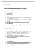
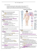
inputs and one output, thus we are dealing with a 2-to-1 or 2:1 mux. The schematic diagram for
the 1-bit 2-to-1 mux you will build is shown in Figure 1. The control/select input, s, indicates
that the output is identical to the a input when the select signal is low (0) and identical to the b
input when the select signal is high (1). Build the multiplexer in Digital as shown in Figure 1.
1
We choose 4-bit (rather than 32-bit) operands because the 4-bit circuitry is much less tedious to construct and
debug.
Version 1.1 Spring 2024 2
, Figure 1. A 2-to-1 mulitplexer.
When done building your schematic, save it with the name two_bit_mux in the Lab2 folder.
(Make sure it is saved in the Lab2 folder so you don’t have to hunt for it later!) Digital will
automatically append the .dig extension.
S A B Y
0 0 0 0
0 0 1 0
0 1 0 1
0 1 1 1
1 0 0 0
1 0 1 1
1 1 0 0
1 1 1 1
Table 1: Truth table for a 1-bit 2-to-1 mux.
The truth table of 2-to-1 mux is shown in Table 1. Click on the Simulation menu and select Start
of Simulation. A shortcut is to click on the triangle icon to the right of the trash icon. Satisfy
yourself that your circuit correctly implements the truth table in Table 1. Once you are satisfied,
Version 1.1 Spring 2024 3
the Arithmetic Logic Unit (ALU)
Prerequisites: Before beginning this lab, you must:
Understand how to use the tool flow (See the installation guide and Lab 0)
Understand the operation of mulitplexers and decoders
Understand 1’s complement and 2’s complement
Have the components available from Lab 1
Equipment: Personal computer with the required software installed.
Files to copy from Lab 1: (all the .dig files)
half_adder.dig
incrementer.dig
full_adder.dig
four_bit_adder.dig
Files to download:
four_bit_mux_top.v
four_bit_mux_stim.txt
alu_top.v
alu_add.v
Objectives: When you have completed this lab, you will be able to:
Build, simulate, and debug a 2-to-1 multiplexer circuit.
Build, simulate, and debug a 4-bit, 2-to-1 multiplexer circuit.
• Use seven-segment displays.
• Build, test, and debug an elementary arithmetic and logic unit (ALU).
• Describe the arithmetic and logical operations of which the ALU is capable.
• Describe the input control line values that correspond to each operation of the ALU.
• Generate tests to verify the operation of the ALU in simulation.
Introduction
In this lab you will continue constructing modules that will be used in assembling the
microprocessor. Our concern in this lab is with circuits that control the flow of data through our
system. You will use the data-flow-control circuit you create in this lab, a 4-bit 2-to-1
multiplexer, to make the microprocessor capable of routing data to appropriate locations. You
will also use seven-segment displays. This will enable you to display numeric values in an easy-
to-read format, which is much nicer than looking at binary values.
In Lab 1 you built combinational logic circuits of increasing complexity. In this laboratory we will
build upon these modules and combine them to form a more complex combinational logic
circuit: the arithmetic logic unit (ALU). The ALU in a microprocessor is the unit that performs all
Version 1.1 Spring 2024 1
,of the arithmetic operations (such as add, subtract, negate, etc.) and all of the logical
operations (such as 1’s complement, AND, OR, etc.) Because this is an introductory class, we
will limit the number of operations our ALU will perform so that we can limit the complexity of
the design. Conceptually, however, your ALU will be no different from the ALU in the personal
computer you use for performing these digital-logic simulations.
Our ALU, like all ALU’s, will be a combinational logic circuit. It will have two data input ports
(each of which will accept 4-bit binary data values1) and it will have a carry input. These data
values are known as operands. Our ALU will be capable of operating on either one operand
(e.g., performing a 1’s complement operation), or two operands (e.g., performing the sum, A+B)
and will produce a 4-bit result (plus a possible carry). The ALU will be controlled by a set of
input control signals. These input control signals will determine which operation the ALU will
perform. It will be left as an exercise at the end of this lab to create a table that lists the
operations the ALU performs for each set of input control signals.
Warning: Use the signal and circuit names provided! Verilog does not allow names to start
with a number or names that have dashes!
Create a folder named Lab2. Into that folder, copy the files listed above from Lab1. Be sure to
only copy the required files. While it is tempting to do Lab 2 in the same directory where you
did Lab 1, it is advisable to start in a fresh directory in case something goes wrong. That way,
you still have the pristine Lab 1 results to copy again. In addition, this means that the Lab 2
folder will only have the files necessary for Lab 2.
Once you’ve copied the files from your Lab1 folder, download the files provided for Lab 2 and
place them in the Lab2 folder. Now, you’re ready to start!
NOTE: You are required to design the circuits as presented in this document. Even though
Digital supplies many of the functions we will design, you are not to use them. For example, we
will design our multiplexer so you are NOT to use the multiplexer available in Digital.
Task 2-1: Build and Test a 1-bit 2-to-1 Multiplexer
When we discuss the architecture of the microprocessor in Labs 3 and 4, we will find that
hardware is needed that allows the executing program to select the route along which data
flows. The component that we will need to perform this function is the multiplexer, or mux. A
mux is a device that can be controlled to route one of its input signals to its sole output.
Therefore, a mux is characterized by its number of signal inputs. In our case, we have two
inputs and one output, thus we are dealing with a 2-to-1 or 2:1 mux. The schematic diagram for
the 1-bit 2-to-1 mux you will build is shown in Figure 1. The control/select input, s, indicates
that the output is identical to the a input when the select signal is low (0) and identical to the b
input when the select signal is high (1). Build the multiplexer in Digital as shown in Figure 1.
1
We choose 4-bit (rather than 32-bit) operands because the 4-bit circuitry is much less tedious to construct and
debug.
Version 1.1 Spring 2024 2
, Figure 1. A 2-to-1 mulitplexer.
When done building your schematic, save it with the name two_bit_mux in the Lab2 folder.
(Make sure it is saved in the Lab2 folder so you don’t have to hunt for it later!) Digital will
automatically append the .dig extension.
S A B Y
0 0 0 0
0 0 1 0
0 1 0 1
0 1 1 1
1 0 0 0
1 0 1 1
1 1 0 0
1 1 1 1
Table 1: Truth table for a 1-bit 2-to-1 mux.
The truth table of 2-to-1 mux is shown in Table 1. Click on the Simulation menu and select Start
of Simulation. A shortcut is to click on the triangle icon to the right of the trash icon. Satisfy
yourself that your circuit correctly implements the truth table in Table 1. Once you are satisfied,
Version 1.1 Spring 2024 3