Signal usage and analysis
,Table of contents
1 Sensors ............................................................................................................................................ 4
1.1 Pressure sensor ....................................................................................................................... 4
1.2 Temperature sensor ................................................................................................................ 4
1.2.1 Thermocouple (Seeback effect) ...................................................................................... 4
1.2.2 Thermistors (Resistive sensor Resistance Temperature Detectors (RTD)) .............................................. 5
1.3 Acceleration sensor ................................................................................................................. 5
1.4 Wheatstone bridge .................................................................................................................. 6
1.5 Capacitors and inductors as sensors ....................................................................................... 6
2 Measurement of signals .................................................................................................................. 7
3 Filtering............................................................................................................................................ 8
3.1 Complex impedance ................................................................................................................ 8
3.2 Basic circuits ............................................................................................................................ 8
3.3 Low-pass filters ........................................................................................................................ 9
3.4 High-pass filters ....................................................................................................................... 9
3.5 Second-order filters ............................................................................................................... 10
4 Operational amplifiers................................................................................................................... 10
4.1 Inverting amplifier ................................................................................................................. 11
4.2 Non-inverting amplifier ......................................................................................................... 11
4.3 Voltage follower .................................................................................................................... 11
4.4 Active filtering ....................................................................................................................... 11
4.4.1 Low pass ........................................................................................................................ 11
4.4.2 High pass........................................................................................................................ 12
5 Number systems............................................................................................................................ 12
5.1 Binary numbers ..................................................................................................................... 12
5.1.1 Binary fractions.............................................................................................................. 13
5.1.2 Adding up binary numbers ............................................................................................ 13
5.1.3 One’s and two’s component ......................................................................................... 13
5.2 Hexadecimal numbers ........................................................................................................... 14
5.3 Octal numbers ....................................................................................................................... 14
6 Boolean algebra............................................................................................................................. 14
6.1 Truth table ............................................................................................................................. 14
6.2 Morgan’s rules ....................................................................................................................... 15
6.3 Other rules............................................................................................................................. 15
7 Logic circuits .................................................................................................................................. 15
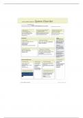
8 Sequential logic circuits ................................................................................................................. 16
, 8.1 Latches................................................................................................................................... 16
8.2 Flip flops ................................................................................................................................ 17
9 Analog-to-digital conversion ......................................................................................................... 18
9.1 Sampling ................................................................................................................................ 18
9.2 Sample and hold .................................................................................................................... 18
9.3 Quantization .......................................................................................................................... 19
10 Transport of analog and digital data ............................................................................................. 19
10.1 Fiber optics ............................................................................................................................ 19
10.2 Digital data transfer ARINC.................................................................................................... 20
11 Electromagnetic Compatibility (EMC) ........................................................................................... 20
, 1 Sensors
A sensor, also called a transducer, is a device that senses/detects specific physical property (heat,
light, sound, pressure, magnetism, or motion) and transmits a resulting impulse for measurement or
control. Sensors can be grouped to their physical characteristics (electronic sensors or resistive
sensors) or by their physical variable or quantity measured by the sensor. Sensors can also be
grouped based on the domains which they belong, such as thermal, mechanical, chemical, magnetic,
radiant or electrical.
1.1 Pressure sensor
Pressure can be sensed by elastic mechanical elements. The movement of the mechanical elements
can be transduced to obtain an electrical signal. The most common sort of the force and pressure
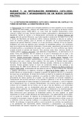
sensors are based on strain gauges and piezoelectric sensors. The
piezoelectric pressure sensor contains a piezoelectric crystal that
generates an electric charge in response to deformation. When a
force or pressure is applied to the crystal, which produces a
displacement, charges are generated within the crystal. The charge
what the sensor will generate can be determined with the formula:
𝑞 = 𝐾𝑝 ∗ 𝑥𝑖
Where q is the charge (in Coulomb), x the displacement due to the external force (in meter) and K
the sensitivity (in Coulombs/meter). To meassure the charge an
capacitor can be added, so the voltage can be meassured. With the
𝑞
formula: 𝐶 = →𝑞 =𝐶∗𝑉
𝑉
With the voltage the pressure can be determined with the formula:
𝑉 = 𝐾𝑝 ∗ 𝑝
The Kp depends on the piezoelectric sensor and the corresponding circuit in this formula it will be
given in V/(Nm-2).
1.2 Temperature sensor
There are many ways to measure temperature: mechanical (mercury thermometer), resistive
(thermistors and RTD’s) and the Seebeck effect (thermocouples)
1.2.1 Thermocouple (Seeback effect)
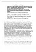
Thermocouples are the most common electrical output sensors to measure temperature, this will be
done by two dissimilar metals that are connected at one end and
connected to a voltage-measuring instrument at the other end.
The temperature difference can be detected by measuring the change
in the voltage across two dissimilar metals at the temperature measurement junction. This voltage
varies with the temperature disparity of the junctions, if the temperature at one junction is known
the temperature of the other junction can be calculated.
When SA and SB are constant you can use the formula:
𝑉
𝑉 = 𝑆𝐴 (𝑇1 − 𝑇2 ) − 𝑆𝐵 (𝑇1 − 𝑇2 ) → 𝑇1 = 𝑇2 +
(𝑆𝐴 − 𝑆𝐵 )
When the SA and SB are not constant another formula is used:
𝑇1 = 𝑇2 + 𝛼0 + 𝛼1 𝑉 + 𝛼2 𝑉 2 + 𝛼3 𝑉 3 +..
,Table of contents
1 Sensors ............................................................................................................................................ 4
1.1 Pressure sensor ....................................................................................................................... 4
1.2 Temperature sensor ................................................................................................................ 4
1.2.1 Thermocouple (Seeback effect) ...................................................................................... 4
1.2.2 Thermistors (Resistive sensor Resistance Temperature Detectors (RTD)) .............................................. 5
1.3 Acceleration sensor ................................................................................................................. 5
1.4 Wheatstone bridge .................................................................................................................. 6
1.5 Capacitors and inductors as sensors ....................................................................................... 6
2 Measurement of signals .................................................................................................................. 7
3 Filtering............................................................................................................................................ 8
3.1 Complex impedance ................................................................................................................ 8
3.2 Basic circuits ............................................................................................................................ 8
3.3 Low-pass filters ........................................................................................................................ 9
3.4 High-pass filters ....................................................................................................................... 9
3.5 Second-order filters ............................................................................................................... 10
4 Operational amplifiers................................................................................................................... 10
4.1 Inverting amplifier ................................................................................................................. 11
4.2 Non-inverting amplifier ......................................................................................................... 11
4.3 Voltage follower .................................................................................................................... 11
4.4 Active filtering ....................................................................................................................... 11
4.4.1 Low pass ........................................................................................................................ 11
4.4.2 High pass........................................................................................................................ 12
5 Number systems............................................................................................................................ 12
5.1 Binary numbers ..................................................................................................................... 12
5.1.1 Binary fractions.............................................................................................................. 13
5.1.2 Adding up binary numbers ............................................................................................ 13
5.1.3 One’s and two’s component ......................................................................................... 13
5.2 Hexadecimal numbers ........................................................................................................... 14
5.3 Octal numbers ....................................................................................................................... 14
6 Boolean algebra............................................................................................................................. 14
6.1 Truth table ............................................................................................................................. 14
6.2 Morgan’s rules ....................................................................................................................... 15
6.3 Other rules............................................................................................................................. 15
7 Logic circuits .................................................................................................................................. 15
8 Sequential logic circuits ................................................................................................................. 16
, 8.1 Latches................................................................................................................................... 16
8.2 Flip flops ................................................................................................................................ 17
9 Analog-to-digital conversion ......................................................................................................... 18
9.1 Sampling ................................................................................................................................ 18
9.2 Sample and hold .................................................................................................................... 18
9.3 Quantization .......................................................................................................................... 19
10 Transport of analog and digital data ............................................................................................. 19
10.1 Fiber optics ............................................................................................................................ 19
10.2 Digital data transfer ARINC.................................................................................................... 20
11 Electromagnetic Compatibility (EMC) ........................................................................................... 20
, 1 Sensors
A sensor, also called a transducer, is a device that senses/detects specific physical property (heat,
light, sound, pressure, magnetism, or motion) and transmits a resulting impulse for measurement or
control. Sensors can be grouped to their physical characteristics (electronic sensors or resistive
sensors) or by their physical variable or quantity measured by the sensor. Sensors can also be
grouped based on the domains which they belong, such as thermal, mechanical, chemical, magnetic,
radiant or electrical.
1.1 Pressure sensor
Pressure can be sensed by elastic mechanical elements. The movement of the mechanical elements
can be transduced to obtain an electrical signal. The most common sort of the force and pressure
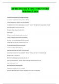
sensors are based on strain gauges and piezoelectric sensors. The
piezoelectric pressure sensor contains a piezoelectric crystal that
generates an electric charge in response to deformation. When a
force or pressure is applied to the crystal, which produces a
displacement, charges are generated within the crystal. The charge
what the sensor will generate can be determined with the formula:
𝑞 = 𝐾𝑝 ∗ 𝑥𝑖
Where q is the charge (in Coulomb), x the displacement due to the external force (in meter) and K
the sensitivity (in Coulombs/meter). To meassure the charge an
capacitor can be added, so the voltage can be meassured. With the
𝑞
formula: 𝐶 = →𝑞 =𝐶∗𝑉
𝑉
With the voltage the pressure can be determined with the formula:
𝑉 = 𝐾𝑝 ∗ 𝑝
The Kp depends on the piezoelectric sensor and the corresponding circuit in this formula it will be
given in V/(Nm-2).
1.2 Temperature sensor
There are many ways to measure temperature: mechanical (mercury thermometer), resistive
(thermistors and RTD’s) and the Seebeck effect (thermocouples)
1.2.1 Thermocouple (Seeback effect)
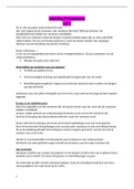
Thermocouples are the most common electrical output sensors to measure temperature, this will be
done by two dissimilar metals that are connected at one end and
connected to a voltage-measuring instrument at the other end.
The temperature difference can be detected by measuring the change
in the voltage across two dissimilar metals at the temperature measurement junction. This voltage
varies with the temperature disparity of the junctions, if the temperature at one junction is known
the temperature of the other junction can be calculated.
When SA and SB are constant you can use the formula:
𝑉
𝑉 = 𝑆𝐴 (𝑇1 − 𝑇2 ) − 𝑆𝐵 (𝑇1 − 𝑇2 ) → 𝑇1 = 𝑇2 +
(𝑆𝐴 − 𝑆𝐵 )
When the SA and SB are not constant another formula is used:
𝑇1 = 𝑇2 + 𝛼0 + 𝛼1 𝑉 + 𝛼2 𝑉 2 + 𝛼3 𝑉 3 +..