🔬
1 MICROSCOPY BASICS
Gestudeerd Not yet
Gezien Processed
Slides 93
Key concepts
1. Wave-like properties of light
2. Lens theory
3. Optical train of compound microscope
4. Properties of optics
5. Contrast enhancement
Basics of Light Microscopy
Introduction
A microscope must accomplish three tasks:
1. Magnification: produce a magnified image of the specimen
2. Resolution: Separate the details in the image
3. Contrast: Render the details visible to the eye, camera, or other imaging device
1.1 Wave-like properties of light
Visible light is a fraction of the EM-spectrum
This ranges from radio waves to gamma rays.
Waves have different properties, such as wavelength, frequency, amplitude, speed, phase and polarisation.
The human eye can only detect visible waves ~ from 400-700nm (blue UV-ish→red IFR-ish).
Higher wavelengths are lower in energy
Lower wavelengths are higher in energy, and are capable of ionizing
Visible light slows down in media other than vacuum.
A wave will undergo certain behaviors when it encounters the end of the medium:
Reflection off the boundary and some transmission into the new medium.
Refraction of the transmitted wave, if it approaches the boundary at an angle
Diffraction of the wave around the object, if the boundary is an obstacle implemented within the medium, and if the dimensions of the obstacle are smaller than the
wavelength of the wave.
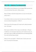
1.1.1 Reflection
Specular reflection: object with surface properties smaller than λ of light → all incident light reflected
θi = θr
Diffuse reflection: irregularities on surface of object are larger than λ of light → light reflects off in all directions
1 MICROSCOPY BASICS 1
1
, 1.1.2 Refraction
Light bends as it is slowed down while entering from air, into a medium.
The refractive index (n) = speed of light in vacuum (c) / speed in medium (v)
c
n=
v
Snell’s law: the angle which light bends with, becomes smaller (bends towards the normal) as the refractive index is bigger.
sin θ1 n2
=
sin θ2
n1
Dispersion, or color-dependent refraction, divides white light into its constitutent spectral components (colors)
Refraction depends on wavelength: a lower λ will refract more than a higher λ.
As a result, the refraction angle will also vary.
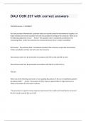
1.1.3 Diffraction
As light waves pass near a barrier and bend around it, it scatters
Single-slit optical diffraction experiment
A slit with an aperture width (d, or opening) more narrow than the wavelength λ of the light that falls on it, will cause the light to bend in a diffraction pattern.
λ
sin θ =
d
θ = angle between the incident central propagation direction and the first minimum of the diffraction pattern.
Diffraction pattern: bright central maximum, flanked by secondary minima, with the intensity of the minima decreasing as the distance from the center increases.
Diffraction limits resolving power: optical instrument’s ability to produce separate images of two adjacent points.
Young’s double-slit experiment
Interference describes the addition of different parts of a wave traveling by
different paths
Constructive: Two interfering waves have displacement in the same
direction. There is no phase shift, the frequency of the wave stays the same
but the amplitude will increase.
Destructive: Displacement in the opposite direction.
Interference fringes form a pattern of many maxima and minima, more
pronounced than the single-split diffraction pattern.
Direct relationship between the position of maxima and minima with the
distance between the two openings or the size of opening A.
1.2 Lens Theory
1.2.1 Standardized rules
Assumed that the lens that the light falls on, is a perfect, convex lens, free of aberration.
Focal point: point in which lenses focus light that travels in parallel waves.
Light emanating from the focal point, shining light on the lens, will travel further in a parallel manner.
Light traveling through the center of the lens, will not refract, but rather move forward in a straight line.
A perfect lens has two focal points. A plane wave passing through the lens will fall in one of these two points, depending on whether the light rays enter from the left or
right side of the lens.
Focal distance: distance between the focal point and the lens.
1.2.2. Equations
The Lens Maker’s Equation
1 1 1
+ =
do
di
f
The Lateral Magnification (M)
1 MICROSCOPY BASICS 2
2
, The distance of the image from the lens di is directly related to the distance of the object from the lens do and the focal distance f.
The ratio of the height of the image hi and the height of the object ho is related to their respective distances.
hi f di
M= = =−
ho f − do
do
1.2.3 Images
Real vs. virtual
Real Image Virtual Image
Light rays diverge, need to be
Refraction type on the other side traced back to the side of the
Light rays focus in one point
of the lens object → form a point on this
side
Object length > focal length
Object position Object length < focal length
(further away)
Magnification (M), image Negative, inverted Positive, upright
Image formation depending on the position of the object
Case Object Position (d) Image Position Image Size Image Nature
1. d ~ ∞ (very far) At focus f Highly diminished (point) Real, inverted
2. d > 2f Between f and 2f Diminished Real, inverted
3. d = 2f At 2f Same size as object Real, inverted
4. 2f > d > f Beyond 2f Magnified Real, inverted
5. d=f At infinity Infinitely large No image (light emerges from lens in parallel → second lens needed for focus)
6. d<f On same side as object Magnified Virtual, upright
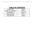
1.3 Optical Train of Compound Microscope
1.3.1 Anatomy of the Microscope
Light Source → Condenser (focuses light) → Specimen / Sample → Objective Lens (first magnification) → Tube Lens (infinity system) → Eyepiece (oculars for second
magnification) → Eye
1. Lamphouse (Lamp + Collector lens)
Lens placed in front of the light source (tungsten-halogen)
Projects an image of the light source onto the plane of the condenser’s aperture
diaphragm
Near the lamp side, the field diaphragm is integrated.
This diaphragm controls the diameter of the light bundle passing through the
specimen (size of the illuminated field).
2. Substage condenser
Gathers the light coming from the light source and concentrates that light in a collection of parallel beams onto the specimen.
Light source comes to focus at the level of the aperture diaphragm (front focal plane of the condenser)
Controls the angular aperture of the cone of light traversing the condenser toward the specimen
3. Objective
Gathers light passing through the specimen and projects a magnified, inverted image of the specimen, that is focused onto the intermediate image plane
Center of the fixed eyepiece field diaphragm
Aperture determines the size of the view-field seen by the microscopist.
Extra structures possible
Darkfield microscopy: + iris
Counteracting spherical aberration: + correcting collar
Phase contrast microscopy: + phase plate
Upright microscope: objectives are above the stage → looks down at the specimen on a glass slide
Inverted microscope: objective lenses are below stage → imaging of cells at the bottom of culture flasks/dishes
4. Eyepiece / ocular lens
Captures the focused, magnified real image projected by the objective
Magnifies that image a second time as a virtual image
1 MICROSCOPY BASICS 3
3
, Image projected by the objective will be projected on the retina and seen at the plane of the fixed diaphragm, as if it were a virtual image.
1.3.2 Infinity-corrected objectives
Finite-conjugate objectives form a direct, intermediate image at fixed tube length → ‘mechanical tube length’
Infinity-corrected objectives do not project the image directly onto the intermediate image plane, but the light is focused to infinity.
Because the parallel rays are focused to infinity, a second tube lens is also needed, which forms the image at its focal plane.
1.3.3 Conjugate planes - Köhler Illumination
Successive planes of common focus in the image-forming path and the illuminating path.
Together, the conjugate planes generate a uniform illumination with optimal resolution.
Image-forming path conjugate planes Illumination path conjugate planes
Correspond to the object (specimen, field diaphragm, Correspond to the source (lamp, diaphragm, pupil)
image planes)
Affect brightness, resolution and contrast.
Form the actual magnified picture of the sample.
Lamp filament is focused in the back focal plane of the
Field diaphragm is focused in the specimen plane. objective.
Variable field diaphragm → Focused specimen on the Lamp filament → Variable Condenser aperture
microscope stage → Fixed diaphragm of the eyepiece diaphragm → Back focal plane of the Objective → The
→ Retina of the eye or sensor of an imaging device eyepoint (exit pupil) of the eyepiece, iris of the human
eye
1.4 Properties of Optics
1.4.1 Resolution
When light from the various points of a specimen passes through the objective and is reconstituted as the image, the various points of the specimen appear in the image as
small concentric circles → Airy patterns, caused by the diffraction of light
Airy disk: central disk. The smaller the disks projected by the objective in forming the image, the finer the detail of the specimen, because the disks are less likely to
overlap.
The ability to distuinguish details, resolving the maxima between points = resolution.
Limit ~ 200nm (+/- diameter of airy pattern)
Diffraction imposes a resolution limit → when combining two patterns, a certain ‘rayleigh limit’ with ~25% intensity drop occurs 0.61λ
d=
Abbe’s formula for optical resolution limit NA
d = smallest distance tha can still be resolved between two points λ
d=
2n ∗ sin α
α = the sine of 1/2 the angular aperture of the objective (angle with which the objective can capture light)
NA = numerical aperture → # of diffraction patterns that can be captured
Two points are just resolved when one airy disk coincides with the first minimum of the other.
Numerical Aperture (NA)
n = refractive index of medium between specimen and objective (air/water/etc.)
A higher NA → wider light cone → more resolution and light-gathering power
n ∗ sin α = NA
Working Distance (WD)
The distance between the front lens of the objective and the specimen when in focus
As NA increases, WD decreases → high-NA lenses have to gather light at wide angles, so the front lens must be very close to the specimen.
1 MICROSCOPY BASICS 4
4
1 MICROSCOPY BASICS
Gestudeerd Not yet
Gezien Processed
Slides 93
Key concepts
1. Wave-like properties of light
2. Lens theory
3. Optical train of compound microscope
4. Properties of optics
5. Contrast enhancement
Basics of Light Microscopy
Introduction
A microscope must accomplish three tasks:
1. Magnification: produce a magnified image of the specimen
2. Resolution: Separate the details in the image
3. Contrast: Render the details visible to the eye, camera, or other imaging device
1.1 Wave-like properties of light
Visible light is a fraction of the EM-spectrum
This ranges from radio waves to gamma rays.
Waves have different properties, such as wavelength, frequency, amplitude, speed, phase and polarisation.
The human eye can only detect visible waves ~ from 400-700nm (blue UV-ish→red IFR-ish).
Higher wavelengths are lower in energy
Lower wavelengths are higher in energy, and are capable of ionizing
Visible light slows down in media other than vacuum.
A wave will undergo certain behaviors when it encounters the end of the medium:
Reflection off the boundary and some transmission into the new medium.
Refraction of the transmitted wave, if it approaches the boundary at an angle
Diffraction of the wave around the object, if the boundary is an obstacle implemented within the medium, and if the dimensions of the obstacle are smaller than the
wavelength of the wave.
1.1.1 Reflection
Specular reflection: object with surface properties smaller than λ of light → all incident light reflected
θi = θr
Diffuse reflection: irregularities on surface of object are larger than λ of light → light reflects off in all directions
1 MICROSCOPY BASICS 1
1
, 1.1.2 Refraction
Light bends as it is slowed down while entering from air, into a medium.
The refractive index (n) = speed of light in vacuum (c) / speed in medium (v)
c
n=
v
Snell’s law: the angle which light bends with, becomes smaller (bends towards the normal) as the refractive index is bigger.
sin θ1 n2
=
sin θ2
n1
Dispersion, or color-dependent refraction, divides white light into its constitutent spectral components (colors)
Refraction depends on wavelength: a lower λ will refract more than a higher λ.
As a result, the refraction angle will also vary.
1.1.3 Diffraction
As light waves pass near a barrier and bend around it, it scatters
Single-slit optical diffraction experiment
A slit with an aperture width (d, or opening) more narrow than the wavelength λ of the light that falls on it, will cause the light to bend in a diffraction pattern.
λ
sin θ =
d
θ = angle between the incident central propagation direction and the first minimum of the diffraction pattern.
Diffraction pattern: bright central maximum, flanked by secondary minima, with the intensity of the minima decreasing as the distance from the center increases.
Diffraction limits resolving power: optical instrument’s ability to produce separate images of two adjacent points.
Young’s double-slit experiment
Interference describes the addition of different parts of a wave traveling by
different paths
Constructive: Two interfering waves have displacement in the same
direction. There is no phase shift, the frequency of the wave stays the same
but the amplitude will increase.
Destructive: Displacement in the opposite direction.
Interference fringes form a pattern of many maxima and minima, more
pronounced than the single-split diffraction pattern.
Direct relationship between the position of maxima and minima with the
distance between the two openings or the size of opening A.
1.2 Lens Theory
1.2.1 Standardized rules
Assumed that the lens that the light falls on, is a perfect, convex lens, free of aberration.
Focal point: point in which lenses focus light that travels in parallel waves.
Light emanating from the focal point, shining light on the lens, will travel further in a parallel manner.
Light traveling through the center of the lens, will not refract, but rather move forward in a straight line.
A perfect lens has two focal points. A plane wave passing through the lens will fall in one of these two points, depending on whether the light rays enter from the left or
right side of the lens.
Focal distance: distance between the focal point and the lens.
1.2.2. Equations
The Lens Maker’s Equation
1 1 1
+ =
do
di
f
The Lateral Magnification (M)
1 MICROSCOPY BASICS 2
2
, The distance of the image from the lens di is directly related to the distance of the object from the lens do and the focal distance f.
The ratio of the height of the image hi and the height of the object ho is related to their respective distances.
hi f di
M= = =−
ho f − do
do
1.2.3 Images
Real vs. virtual
Real Image Virtual Image
Light rays diverge, need to be
Refraction type on the other side traced back to the side of the
Light rays focus in one point
of the lens object → form a point on this
side
Object length > focal length
Object position Object length < focal length
(further away)
Magnification (M), image Negative, inverted Positive, upright
Image formation depending on the position of the object
Case Object Position (d) Image Position Image Size Image Nature
1. d ~ ∞ (very far) At focus f Highly diminished (point) Real, inverted
2. d > 2f Between f and 2f Diminished Real, inverted
3. d = 2f At 2f Same size as object Real, inverted
4. 2f > d > f Beyond 2f Magnified Real, inverted
5. d=f At infinity Infinitely large No image (light emerges from lens in parallel → second lens needed for focus)
6. d<f On same side as object Magnified Virtual, upright
1.3 Optical Train of Compound Microscope
1.3.1 Anatomy of the Microscope
Light Source → Condenser (focuses light) → Specimen / Sample → Objective Lens (first magnification) → Tube Lens (infinity system) → Eyepiece (oculars for second
magnification) → Eye
1. Lamphouse (Lamp + Collector lens)
Lens placed in front of the light source (tungsten-halogen)
Projects an image of the light source onto the plane of the condenser’s aperture
diaphragm
Near the lamp side, the field diaphragm is integrated.
This diaphragm controls the diameter of the light bundle passing through the
specimen (size of the illuminated field).
2. Substage condenser
Gathers the light coming from the light source and concentrates that light in a collection of parallel beams onto the specimen.
Light source comes to focus at the level of the aperture diaphragm (front focal plane of the condenser)
Controls the angular aperture of the cone of light traversing the condenser toward the specimen
3. Objective
Gathers light passing through the specimen and projects a magnified, inverted image of the specimen, that is focused onto the intermediate image plane
Center of the fixed eyepiece field diaphragm
Aperture determines the size of the view-field seen by the microscopist.
Extra structures possible
Darkfield microscopy: + iris
Counteracting spherical aberration: + correcting collar
Phase contrast microscopy: + phase plate
Upright microscope: objectives are above the stage → looks down at the specimen on a glass slide
Inverted microscope: objective lenses are below stage → imaging of cells at the bottom of culture flasks/dishes
4. Eyepiece / ocular lens
Captures the focused, magnified real image projected by the objective
Magnifies that image a second time as a virtual image
1 MICROSCOPY BASICS 3
3
, Image projected by the objective will be projected on the retina and seen at the plane of the fixed diaphragm, as if it were a virtual image.
1.3.2 Infinity-corrected objectives
Finite-conjugate objectives form a direct, intermediate image at fixed tube length → ‘mechanical tube length’
Infinity-corrected objectives do not project the image directly onto the intermediate image plane, but the light is focused to infinity.
Because the parallel rays are focused to infinity, a second tube lens is also needed, which forms the image at its focal plane.
1.3.3 Conjugate planes - Köhler Illumination
Successive planes of common focus in the image-forming path and the illuminating path.
Together, the conjugate planes generate a uniform illumination with optimal resolution.
Image-forming path conjugate planes Illumination path conjugate planes
Correspond to the object (specimen, field diaphragm, Correspond to the source (lamp, diaphragm, pupil)
image planes)
Affect brightness, resolution and contrast.
Form the actual magnified picture of the sample.
Lamp filament is focused in the back focal plane of the
Field diaphragm is focused in the specimen plane. objective.
Variable field diaphragm → Focused specimen on the Lamp filament → Variable Condenser aperture
microscope stage → Fixed diaphragm of the eyepiece diaphragm → Back focal plane of the Objective → The
→ Retina of the eye or sensor of an imaging device eyepoint (exit pupil) of the eyepiece, iris of the human
eye
1.4 Properties of Optics
1.4.1 Resolution
When light from the various points of a specimen passes through the objective and is reconstituted as the image, the various points of the specimen appear in the image as
small concentric circles → Airy patterns, caused by the diffraction of light
Airy disk: central disk. The smaller the disks projected by the objective in forming the image, the finer the detail of the specimen, because the disks are less likely to
overlap.
The ability to distuinguish details, resolving the maxima between points = resolution.
Limit ~ 200nm (+/- diameter of airy pattern)
Diffraction imposes a resolution limit → when combining two patterns, a certain ‘rayleigh limit’ with ~25% intensity drop occurs 0.61λ
d=
Abbe’s formula for optical resolution limit NA
d = smallest distance tha can still be resolved between two points λ
d=
2n ∗ sin α
α = the sine of 1/2 the angular aperture of the objective (angle with which the objective can capture light)
NA = numerical aperture → # of diffraction patterns that can be captured
Two points are just resolved when one airy disk coincides with the first minimum of the other.
Numerical Aperture (NA)
n = refractive index of medium between specimen and objective (air/water/etc.)
A higher NA → wider light cone → more resolution and light-gathering power
n ∗ sin α = NA
Working Distance (WD)
The distance between the front lens of the objective and the specimen when in focus
As NA increases, WD decreases → high-NA lenses have to gather light at wide angles, so the front lens must be very close to the specimen.
1 MICROSCOPY BASICS 4
4