BIREFINGS IRI
08 APP SEGMENTS & REVERSAL PROCEDURES
Page
APPROACH SEGMENTS 2
1. ARRIVAL SEGMENT 6
2. INITIAL SEGMENT
Flight procedures for racetrack & reversal proc 7
a. Procedure turns 10
i. 45°/180° procedure turn 10
ii. 80°/260° procedure turn 11
b. Base turn 13
c. Racetrack pattern 15
d. Back to inbound course 18
3. INTERMEDIATE APPROACH 19
4. FINAL APPROACH 21
a. NPA with FAF 22
b. FAF Crossing 23
c. Stepdown fixes 24
d. Stepdown fix with DME 25
e. NPA without FAF 26
f. Precision Approach 27
g. Determination of DA/DH 28
5. MISSED APPROACH SEGMENT 29
a. Missed approach gradient 32
b. Initial phase 33
c. Intermediate phase 33
d. Final phase 33
e. Go-Around or T/G AT school 36
Briefings IRI 08 APP SEG & REV PROC rev 03: 05 22 Page 1
,REVIEW OF PUBLISHED INSTRUCTIONS 37
Briefings IRI 08 APP SEG & REV PROC rev 03: 05 22 Page 2
, APPROACH SEGMENTS
UP TO 5 different segments for an instrument approach
1. ARRIVAL
2. INITIAL
3. INTERMEDIATE
4. FINAL
5. MISSED APP
Briefings IRI 08 APP SEG & REV PROC rev 03: 05 22 Page 3
,Briefings IRI 08 APP SEG & REV PROC rev 03: 05 22 Page 4
,With difference between each: SPEEDS
With difference between each: ALLOWED MANEUVERING
E.g. ROD in the final approach segment of a procedure without FAF
Briefings IRI 08 APP SEG & REV PROC rev 03: 05 22 Page 5
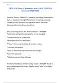
,With difference between each: OBSTACLE CLEARANCE
JEPPESEN ATC P203:
FLIGHT PROCEDURES (DOC 8168) - GENERAL REQUIREMENTS : 1 GENERAL
REQUIREMENTS
1.3.4 The minimum obstacle clearance (MOC) is provided for the whole width of the
primary area.
In the secondary area, MOC is provided at the inner edges reducing to zero at the outer
edges (see Figure I-2-1-2).
Briefings IRI 08 APP SEG & REV PROC rev 03: 05 22 Page 6
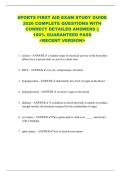
, 1. ARRIVAL SEGMENT
• LIMITS: Enroute to the Initial Approach Fix (IAF)
EBCI VOR 25
EBBR STAR 10-2
Briefings IRI 08 APP SEG & REV PROC rev 03: 05 22 Page 7
, 2. INITIAL SEGMENT
Flight procedures for racetrack & reversal procedures
• LIMITS: from (IAF) to Intermediate Fix (IF)
EBCI ILS 25
• OBSTACLE CLEARANCE: 1000 ft in primary area
Briefings IRI 08 APP SEG & REV PROC rev 03: 05 22 Page 8
, • SPEED (CAT A): 90 < IAS < 150 kts,
o Except racetrack & reversal (110 kts)
• 3.3 FLT PROC FOR RACETRACK & REVERSAL PROCEDURE
3.3.2 Speed restrictions.
– These may be specified in addition to, or instead of, aircraft category
restrictions.
– The speeds must not be exceeded to ensure that the aircraft remains
within the limits of the protected areas.
3.3.3 Bank angle.
– Procedures are based on average achieved bank angle of 25°, or giving a rate of
turn of 3°/second, whichever is less.
3.3.4 Descent.
– The aircraft shall cross the fix or facility and fly outbound on the specified
track, descending as necessary to the procedure altitude/height but no lower
than the minimum crossing altitude/height associated with that segment.
– If a further descent is specified after the inbound turn, this descent shall not be
started until the aircraft is established on the inbound track.
o “Established” is considered as being
§ Within half full scale deflection for ILS & VOR
§ Or within ± 5° of the required bearing for the NDB.
3.3.6 Wind effect.
3.3.6.1 To achieve a stabilized approach, due allowance should be made in both
heading and timing (Ed note: 1 sec / kt, with max 30 sec) to compensate for the
effects of wind so that the aircraft regains the inbound track as accurately and
expeditiously as possible.
In making these corrections, full use should be made of the indications available from
the aid and from estimated or known winds.
This is particularly important for slow aircraft in high wind conditions, when failure to
compensate may render the procedure unflyable (i.e. the aircraft may pass the fix
before establishing on the inbound track) and it could depart outside the protected
area).
3.3.6.2 When a DME distance or radial/bearing is specified, it shall not be exceeded
when flying on the outbound track.
Briefings IRI 08 APP SEG & REV PROC rev 03: 05 22 Page 9
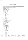
, 3.3.7 Descent rates.
• The specified timings and procedure altitudes are based on rates of descent that
DO NOT exceed the values shown in Table I-4-3-1.
* Maximum/minimum descent for 1-minute nominal outbound time in m (ft)
3.3.8 Shuttle.
• A shuttle is normally prescribed where the descent required between the end of
initial approach and the beginning of final approach exceeds the values shown
in Table I-4-3-1.
* Maximum/minimum descent for 1-minute nominal outbound time in m (ft)
• NOTE:
A shuttle is descent or climb conducted in a holding pattern.
Briefings IRI 08 APP SEG & REV PROC rev 03: 05 22 Page 10
08 APP SEGMENTS & REVERSAL PROCEDURES
Page
APPROACH SEGMENTS 2
1. ARRIVAL SEGMENT 6
2. INITIAL SEGMENT
Flight procedures for racetrack & reversal proc 7
a. Procedure turns 10
i. 45°/180° procedure turn 10
ii. 80°/260° procedure turn 11
b. Base turn 13
c. Racetrack pattern 15
d. Back to inbound course 18
3. INTERMEDIATE APPROACH 19
4. FINAL APPROACH 21
a. NPA with FAF 22
b. FAF Crossing 23
c. Stepdown fixes 24
d. Stepdown fix with DME 25
e. NPA without FAF 26
f. Precision Approach 27
g. Determination of DA/DH 28
5. MISSED APPROACH SEGMENT 29
a. Missed approach gradient 32
b. Initial phase 33
c. Intermediate phase 33
d. Final phase 33
e. Go-Around or T/G AT school 36
Briefings IRI 08 APP SEG & REV PROC rev 03: 05 22 Page 1
,REVIEW OF PUBLISHED INSTRUCTIONS 37
Briefings IRI 08 APP SEG & REV PROC rev 03: 05 22 Page 2
, APPROACH SEGMENTS
UP TO 5 different segments for an instrument approach
1. ARRIVAL
2. INITIAL
3. INTERMEDIATE
4. FINAL
5. MISSED APP
Briefings IRI 08 APP SEG & REV PROC rev 03: 05 22 Page 3
,Briefings IRI 08 APP SEG & REV PROC rev 03: 05 22 Page 4
,With difference between each: SPEEDS
With difference between each: ALLOWED MANEUVERING
E.g. ROD in the final approach segment of a procedure without FAF
Briefings IRI 08 APP SEG & REV PROC rev 03: 05 22 Page 5
,With difference between each: OBSTACLE CLEARANCE
JEPPESEN ATC P203:
FLIGHT PROCEDURES (DOC 8168) - GENERAL REQUIREMENTS : 1 GENERAL
REQUIREMENTS
1.3.4 The minimum obstacle clearance (MOC) is provided for the whole width of the
primary area.
In the secondary area, MOC is provided at the inner edges reducing to zero at the outer
edges (see Figure I-2-1-2).
Briefings IRI 08 APP SEG & REV PROC rev 03: 05 22 Page 6
, 1. ARRIVAL SEGMENT
• LIMITS: Enroute to the Initial Approach Fix (IAF)
EBCI VOR 25
EBBR STAR 10-2
Briefings IRI 08 APP SEG & REV PROC rev 03: 05 22 Page 7
, 2. INITIAL SEGMENT
Flight procedures for racetrack & reversal procedures
• LIMITS: from (IAF) to Intermediate Fix (IF)
EBCI ILS 25
• OBSTACLE CLEARANCE: 1000 ft in primary area
Briefings IRI 08 APP SEG & REV PROC rev 03: 05 22 Page 8
, • SPEED (CAT A): 90 < IAS < 150 kts,
o Except racetrack & reversal (110 kts)
• 3.3 FLT PROC FOR RACETRACK & REVERSAL PROCEDURE
3.3.2 Speed restrictions.
– These may be specified in addition to, or instead of, aircraft category
restrictions.
– The speeds must not be exceeded to ensure that the aircraft remains
within the limits of the protected areas.
3.3.3 Bank angle.
– Procedures are based on average achieved bank angle of 25°, or giving a rate of
turn of 3°/second, whichever is less.
3.3.4 Descent.
– The aircraft shall cross the fix or facility and fly outbound on the specified
track, descending as necessary to the procedure altitude/height but no lower
than the minimum crossing altitude/height associated with that segment.
– If a further descent is specified after the inbound turn, this descent shall not be
started until the aircraft is established on the inbound track.
o “Established” is considered as being
§ Within half full scale deflection for ILS & VOR
§ Or within ± 5° of the required bearing for the NDB.
3.3.6 Wind effect.
3.3.6.1 To achieve a stabilized approach, due allowance should be made in both
heading and timing (Ed note: 1 sec / kt, with max 30 sec) to compensate for the
effects of wind so that the aircraft regains the inbound track as accurately and
expeditiously as possible.
In making these corrections, full use should be made of the indications available from
the aid and from estimated or known winds.
This is particularly important for slow aircraft in high wind conditions, when failure to
compensate may render the procedure unflyable (i.e. the aircraft may pass the fix
before establishing on the inbound track) and it could depart outside the protected
area).
3.3.6.2 When a DME distance or radial/bearing is specified, it shall not be exceeded
when flying on the outbound track.
Briefings IRI 08 APP SEG & REV PROC rev 03: 05 22 Page 9
, 3.3.7 Descent rates.
• The specified timings and procedure altitudes are based on rates of descent that
DO NOT exceed the values shown in Table I-4-3-1.
* Maximum/minimum descent for 1-minute nominal outbound time in m (ft)
3.3.8 Shuttle.
• A shuttle is normally prescribed where the descent required between the end of
initial approach and the beginning of final approach exceeds the values shown
in Table I-4-3-1.
* Maximum/minimum descent for 1-minute nominal outbound time in m (ft)
• NOTE:
A shuttle is descent or climb conducted in a holding pattern.
Briefings IRI 08 APP SEG & REV PROC rev 03: 05 22 Page 10