RADIO
NAVIGATION
1
–
BASIC
RADIO
PRINCIPLES
BASIC
TERMS
PHASE
DIFFERENCE
MODULATION
TYPE
1
-‐
KEYING
• Radio
waves
travel
at
the
speed
of
light:
• Can
only
be
measured
when
the
signals
have
• Interrupting
the
carrier
wave
to
give
morse
o c
=
3
x
108
m/sec
the
same
frequency
(or
wavelength).
code.
• Will
temporarily
interrupt
the
nav
aid
• Frequency
(f)
–
Number
of
complete
cycles
output
in
order
to
tx
the
morse
code.
per
second.
Measured
in
Hertz
(Hz)
POLARISATION
o 1
cycle
per
second
=
1
Hz
o 1
kHz
=
103
Hz
MODULATION
TYPE
2
-‐
AM
• The
electrical
and
magnetic
components
of
a
o 1
MHz
=
106
Hz
radio
wave
travel
at
right
angle
to
each
o 1
GHz
=
109
Hz
• AM
=
Amplitude
Modulation
other
and
in
the
direction
of
propagation.
• Amplitude
of
the
carrier
wave
is
varied
in
• Plane
of
electrical
component
=
plane
of
• Wavelength
(𝜆)
–
Distance
travelled
in
one
accordance
with
the
audio
signal
amplitude.
polarisation.
complete
cycle.
Measured
in
metres.
• Carrier
wave
frequency
is
kept
constant.
• Transmission
from
vertical
aerial
gives
a
• Oldest
method
apart
from
keying.
vertical
electric
component
and
horizontal
• Time
period
(𝑻)
–
Time
taken
to
complete
• Small
amplitude
areas
give
a
weak
signal
magnetic
component.
once
cycle.
T
=
1
/
f
that
is
prone
to
interference
(especially
• Transmission
from
horizontal
aerial
gives
since
it
operates
in
low
frequency
spectrum)
horizontal
electrical
component
and
vertical
• 𝑪 = 𝝀 × 𝒇
• Modulation
circuit
requires
extra
power
to
magnetic
component.
vary
the
amplitude.
• In
circular
propagation,
both
components
• Low
Frequency
=
Long
Wavelength
spin
about
the
axis
of
advance.
• High
Frequency
=
Short
Wavelength
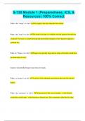
POLAR
DIAGRAMS
ANTENNA
LENGTH
1.
Omnidirectional
• Ideal
antenna
length
is
½
the
wavelength.
2.
Directional
(Inc
unwanted
side
lobes)
• If
not
possible,
then
1/4
,
1/8
etc
will
do.
• Applies
to
both
Tx
and
Rx
aerials.
MODULATION
• Modulation
adds
information
to
an
otherwise
empty
carrier
wave.
, RADIO
NAVIGATION
1
–
BASIC
RADIO
PRINCIPLES
MODULATION
TYPE
3
-‐
FM
MODULATION
TYPE
4
-‐
PULSE
FREQUENCY
SPECTRUM
• FM
=
Frequency
Modulation
• Radio
wave
is
switched
on
and
off
at
regular
• Frequency
range
repeats
(kHz
/
MHz
/
GHz)
• Frequency
of
the
carrier
wave
is
varied
in
intervals,
effectively
forming
pulses
of
radio
o 3
–
30
accordance
with
the
audio
signal
amplitude.
energy.
o 30
–
300
• Carrier
wave
amplitude
is
kept
constant.
• Use
in
radar.
o 300
-‐
3000
• A
+ve
amplitude
=
higher
frequency
• Transmits
0’s
and
1’s
effectively.
• A
–ve
amplitude
=
lower
frequency
• Wave-‐length
can
be
derived
with
𝐶 = 𝜆 × 𝑓
• FM
TX’s
are
simpler
and
cheaper
than
AM
AM
SIDEBANDS
• Lower
modulation
power
required
• Constant
amplitude
=
stronger
• Whenever
a
carrier
is
AM
modulated
by
a
• VHF
operation
=
almost
static
free
frequency
lower
than
itself,
sidebands
are
• Horizontally
polarised
so
suffers
less
from
created.
weather
induced
static
(vertically
polarised)
• Carrier
Wave
=
500
kHz,
Audio
Freq
=
4
kHz
o 4
kHz
is
filtered
out.
• Receivers
are
more
complex.
o 496
kHz
/
500
kHz
/
504
kHz
output
• Wider
frequency
band
required.
• Passband
is
a
filter
used
to
get
rid
of
unwanted
frequencies
so
bandwidth
can
be
reduced.
• Single
Sideband
(SSB)
–
Often
only
1
of
the
outputs
is
TX’d.
The
sideband
carries
the
information
rather
than
the
carrier.
o With
all
TX
power
focused
on
one
sideband,
range
is
increased.
EMMISSION
CODES
• FM
has
many
more
sidebands
than
AM.
• 1st
=
Type
of
modulation
• 2nd
=
Nature
of
modulating
signal
HF
COMMS
&
HF
VOLMET
• 3rd
=
Type
of
information
transmitted
• Use
single
sideband
• HF
SSB
=
J3E
, RADIO
NAVIGATION
1
–
BASIC
RADIO
PRINCIPLES
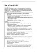
REFRACTION
SURFACE
ATTENUATION
ATTENUATION
&
REFRACTION
BY
FREQ
• Radio
waves
are
refracted
when
travelling
• As
a
radio
wave
passes
over
a
surface
it
• Top
Column
=
A
-‐
RADAR
obliquely
from
a
medium
of
one
density
loses
energy.
to
another
of
different
density.
• Higher
frequencies
are
more
susceptible
as
• Due
to
different
velocities
there
is
a
slight
they
hit
the
surface
more
often.
change
of
wavelength.
• Low
to
high
density
=
slows
down
and
bends
towards
the
normal.
IONOSPHERIC
ATTENUATION
• Types
of
refraction:
• The
ionosphere
and
particles
in
the
o Coastal
(Land
to
sea.
Flying
higher
or
atmosphere
can
absorb
and
block
a
radio
moving
beacon
towards
coast
will
wave.
reduce
effects)
o Atmospheric
(Density
change
with
altitude.
ATMOSOHERIC
/
RADAR
ATTENUATION
o Ionospheric
• When
radar
energy
strikes
water
BASIC
RADIO
CIRCUIT
droplets,
some
energy
is
absorbed
(and
attenuated)
and
some
is
reflected.
REFLECTION
• Human
Ear:
20
Hz
–
20
kHz
• Radio
waves
bounce
off
a
solid
surface.
DOPPLER
EFFECT
• If
two
signals
arrive
at
the
same
time
but
out
of
phase,
there
can
be
fading
/
temporary
• +
VE
Doppler
Shift:
If
the
distance
between
losses.
the
source
and
the
receiver
is
reducing,
the
received
frequency
appears
greater
than
that
transmitted.
DIFFRACTION
• Occurs
because
more
waves
are
detected
than
if
stationary.
• When
a
radio
wave
passes
a
solid
object,
• -‐
VE
Doppler
Shift:
Distance
increasing
/
radio
energy
is
scattered.
frequency
appears
lower.
• Allows
radio
waves
to
be
received
behind
a
• Actual
wavelength
stays
the
same.
mountain.
NAVIGATION
1
–
BASIC
RADIO
PRINCIPLES
BASIC
TERMS
PHASE
DIFFERENCE
MODULATION
TYPE
1
-‐
KEYING
• Radio
waves
travel
at
the
speed
of
light:
• Can
only
be
measured
when
the
signals
have
• Interrupting
the
carrier
wave
to
give
morse
o c
=
3
x
108
m/sec
the
same
frequency
(or
wavelength).
code.
• Will
temporarily
interrupt
the
nav
aid
• Frequency
(f)
–
Number
of
complete
cycles
output
in
order
to
tx
the
morse
code.
per
second.
Measured
in
Hertz
(Hz)
POLARISATION
o 1
cycle
per
second
=
1
Hz
o 1
kHz
=
103
Hz
MODULATION
TYPE
2
-‐
AM
• The
electrical
and
magnetic
components
of
a
o 1
MHz
=
106
Hz
radio
wave
travel
at
right
angle
to
each
o 1
GHz
=
109
Hz
• AM
=
Amplitude
Modulation
other
and
in
the
direction
of
propagation.
• Amplitude
of
the
carrier
wave
is
varied
in
• Plane
of
electrical
component
=
plane
of
• Wavelength
(𝜆)
–
Distance
travelled
in
one
accordance
with
the
audio
signal
amplitude.
polarisation.
complete
cycle.
Measured
in
metres.
• Carrier
wave
frequency
is
kept
constant.
• Transmission
from
vertical
aerial
gives
a
• Oldest
method
apart
from
keying.
vertical
electric
component
and
horizontal
• Time
period
(𝑻)
–
Time
taken
to
complete
• Small
amplitude
areas
give
a
weak
signal
magnetic
component.
once
cycle.
T
=
1
/
f
that
is
prone
to
interference
(especially
• Transmission
from
horizontal
aerial
gives
since
it
operates
in
low
frequency
spectrum)
horizontal
electrical
component
and
vertical
• 𝑪 = 𝝀 × 𝒇
• Modulation
circuit
requires
extra
power
to
magnetic
component.
vary
the
amplitude.
• In
circular
propagation,
both
components
• Low
Frequency
=
Long
Wavelength
spin
about
the
axis
of
advance.
• High
Frequency
=
Short
Wavelength
POLAR
DIAGRAMS
ANTENNA
LENGTH
1.
Omnidirectional
• Ideal
antenna
length
is
½
the
wavelength.
2.
Directional
(Inc
unwanted
side
lobes)
• If
not
possible,
then
1/4
,
1/8
etc
will
do.
• Applies
to
both
Tx
and
Rx
aerials.
MODULATION
• Modulation
adds
information
to
an
otherwise
empty
carrier
wave.
, RADIO
NAVIGATION
1
–
BASIC
RADIO
PRINCIPLES
MODULATION
TYPE
3
-‐
FM
MODULATION
TYPE
4
-‐
PULSE
FREQUENCY
SPECTRUM
• FM
=
Frequency
Modulation
• Radio
wave
is
switched
on
and
off
at
regular
• Frequency
range
repeats
(kHz
/
MHz
/
GHz)
• Frequency
of
the
carrier
wave
is
varied
in
intervals,
effectively
forming
pulses
of
radio
o 3
–
30
accordance
with
the
audio
signal
amplitude.
energy.
o 30
–
300
• Carrier
wave
amplitude
is
kept
constant.
• Use
in
radar.
o 300
-‐
3000
• A
+ve
amplitude
=
higher
frequency
• Transmits
0’s
and
1’s
effectively.
• A
–ve
amplitude
=
lower
frequency
• Wave-‐length
can
be
derived
with
𝐶 = 𝜆 × 𝑓
• FM
TX’s
are
simpler
and
cheaper
than
AM
AM
SIDEBANDS
• Lower
modulation
power
required
• Constant
amplitude
=
stronger
• Whenever
a
carrier
is
AM
modulated
by
a
• VHF
operation
=
almost
static
free
frequency
lower
than
itself,
sidebands
are
• Horizontally
polarised
so
suffers
less
from
created.
weather
induced
static
(vertically
polarised)
• Carrier
Wave
=
500
kHz,
Audio
Freq
=
4
kHz
o 4
kHz
is
filtered
out.
• Receivers
are
more
complex.
o 496
kHz
/
500
kHz
/
504
kHz
output
• Wider
frequency
band
required.
• Passband
is
a
filter
used
to
get
rid
of
unwanted
frequencies
so
bandwidth
can
be
reduced.
• Single
Sideband
(SSB)
–
Often
only
1
of
the
outputs
is
TX’d.
The
sideband
carries
the
information
rather
than
the
carrier.
o With
all
TX
power
focused
on
one
sideband,
range
is
increased.
EMMISSION
CODES
• FM
has
many
more
sidebands
than
AM.
• 1st
=
Type
of
modulation
• 2nd
=
Nature
of
modulating
signal
HF
COMMS
&
HF
VOLMET
• 3rd
=
Type
of
information
transmitted
• Use
single
sideband
• HF
SSB
=
J3E
, RADIO
NAVIGATION
1
–
BASIC
RADIO
PRINCIPLES
REFRACTION
SURFACE
ATTENUATION
ATTENUATION
&
REFRACTION
BY
FREQ
• Radio
waves
are
refracted
when
travelling
• As
a
radio
wave
passes
over
a
surface
it
• Top
Column
=
A
-‐
RADAR
obliquely
from
a
medium
of
one
density
loses
energy.
to
another
of
different
density.
• Higher
frequencies
are
more
susceptible
as
• Due
to
different
velocities
there
is
a
slight
they
hit
the
surface
more
often.
change
of
wavelength.
• Low
to
high
density
=
slows
down
and
bends
towards
the
normal.
IONOSPHERIC
ATTENUATION
• Types
of
refraction:
• The
ionosphere
and
particles
in
the
o Coastal
(Land
to
sea.
Flying
higher
or
atmosphere
can
absorb
and
block
a
radio
moving
beacon
towards
coast
will
wave.
reduce
effects)
o Atmospheric
(Density
change
with
altitude.
ATMOSOHERIC
/
RADAR
ATTENUATION
o Ionospheric
• When
radar
energy
strikes
water
BASIC
RADIO
CIRCUIT
droplets,
some
energy
is
absorbed
(and
attenuated)
and
some
is
reflected.
REFLECTION
• Human
Ear:
20
Hz
–
20
kHz
• Radio
waves
bounce
off
a
solid
surface.
DOPPLER
EFFECT
• If
two
signals
arrive
at
the
same
time
but
out
of
phase,
there
can
be
fading
/
temporary
• +
VE
Doppler
Shift:
If
the
distance
between
losses.
the
source
and
the
receiver
is
reducing,
the
received
frequency
appears
greater
than
that
transmitted.
DIFFRACTION
• Occurs
because
more
waves
are
detected
than
if
stationary.
• When
a
radio
wave
passes
a
solid
object,
• -‐
VE
Doppler
Shift:
Distance
increasing
/
radio
energy
is
scattered.
frequency
appears
lower.
• Allows
radio
waves
to
be
received
behind
a
• Actual
wavelength
stays
the
same.
mountain.