ME20026: TRANSFORMATIVE Open Die Forging: Impression-die and closed die forging:
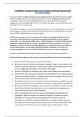
Simplest forging operation Workpiece takes shape of die cavity while being forged between
MANUFACTURING TECHNOLOGIES: Solid workpiece placed between two flat dies and reduced two shaped dies
in height by compressing it Carried out at elevated temperatures
METAL FORGING: o Also called upsetting or flat-die forging o Lowers required forces
Workpiece is shaped by compressive forces applied through various Die surfaces have shallow cavities or incorporate features o Attains enhanced ductility in workpiece
dies and tooling to produce relatively simple forgings
Parts made by forging
o Large rotors for turbines Solid cylindrical
o Gears billet upset
o Bolts and rivets between two
flat dies Parting line
o Cutlery
o Mostly located at largest cross section of part
o Hand tools
o Simple symmetrical shapes
o Structural components for machinery, aircraft and railroads
Straight line at centre of forging
Forged parts have good strength and toughness Uniform o Complex shapes
o Metal flow in a die and material’s grain structure can be controlled deformation of Line may not lie in single plane
o Very reliable for highly stressed and critical applications billet without
Forging requires set of dies and equipment such as a press or powered friction Flash thickness
forging hammer o Estimated 3% of maximum thickness of forging
o Length of land is usually 2-5 times the flash thickness
Comparison of cold forging and hot forging Deformation of
Cold Forging Hot Forging billet with
Requires higher forces Lower forces required friction – causes
o Higher strength of Less good dimensional barrelling
workpiece material accuracy and surface finish
Workpiece must possess
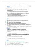
sufficient ductility at room Estimation of forging force in an open-die forging
temperature to undergo operation:
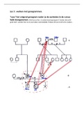
necessary deformation without Draft angles
o F is forging force
cracking o Necessary in almost all forging dies
Parts have good surface finish o Y f is flow stress of material o Facilitates removal of part from die
and good dimensional accuracy o μ is coefficient of friction between workpiece and o Internal draft angles made larger than external draft angles
Forging shrinks both radially and longitudinally upon
Additional finishing operations generally needed die
cooling
o E.g. heat treatment o r is instantaneous radius of workpiece Internal draft angles 7o – 10o
o Modifies properties machining o h is instantaneous height of workpiece External draft angles 3o – 5o
o Obtains accurate final dimensions and good surface finish
o Finishing operations minimised by precision forging
Important example of net-shape or near-net-shape forming
process
F=Y f π r 2 1+ ( 2 μr
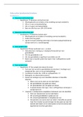
3h ) Selection of radii for corners and fillets
o Ensures smooth flow of metal into die cavity
o Helps improve die life
True stress-strain curves used in calculation of required o Small radii generally undesirable
forging force Adverse effect on metal flow
Tendency to wear rapidly
As a result of stress concentration and thermal
cycling
Simplest forging operation Workpiece takes shape of die cavity while being forged between
MANUFACTURING TECHNOLOGIES: Solid workpiece placed between two flat dies and reduced two shaped dies
in height by compressing it Carried out at elevated temperatures
METAL FORGING: o Also called upsetting or flat-die forging o Lowers required forces
Workpiece is shaped by compressive forces applied through various Die surfaces have shallow cavities or incorporate features o Attains enhanced ductility in workpiece
dies and tooling to produce relatively simple forgings
Parts made by forging
o Large rotors for turbines Solid cylindrical
o Gears billet upset
o Bolts and rivets between two
flat dies Parting line
o Cutlery
o Mostly located at largest cross section of part
o Hand tools
o Simple symmetrical shapes
o Structural components for machinery, aircraft and railroads
Straight line at centre of forging
Forged parts have good strength and toughness Uniform o Complex shapes
o Metal flow in a die and material’s grain structure can be controlled deformation of Line may not lie in single plane
o Very reliable for highly stressed and critical applications billet without
Forging requires set of dies and equipment such as a press or powered friction Flash thickness
forging hammer o Estimated 3% of maximum thickness of forging
o Length of land is usually 2-5 times the flash thickness
Comparison of cold forging and hot forging Deformation of
Cold Forging Hot Forging billet with
Requires higher forces Lower forces required friction – causes
o Higher strength of Less good dimensional barrelling
workpiece material accuracy and surface finish
Workpiece must possess
sufficient ductility at room Estimation of forging force in an open-die forging
temperature to undergo operation:
necessary deformation without Draft angles
o F is forging force
cracking o Necessary in almost all forging dies
Parts have good surface finish o Y f is flow stress of material o Facilitates removal of part from die
and good dimensional accuracy o μ is coefficient of friction between workpiece and o Internal draft angles made larger than external draft angles
Forging shrinks both radially and longitudinally upon
Additional finishing operations generally needed die
cooling
o E.g. heat treatment o r is instantaneous radius of workpiece Internal draft angles 7o – 10o
o Modifies properties machining o h is instantaneous height of workpiece External draft angles 3o – 5o
o Obtains accurate final dimensions and good surface finish
o Finishing operations minimised by precision forging
Important example of net-shape or near-net-shape forming
process
F=Y f π r 2 1+ ( 2 μr
3h ) Selection of radii for corners and fillets
o Ensures smooth flow of metal into die cavity
o Helps improve die life
True stress-strain curves used in calculation of required o Small radii generally undesirable
forging force Adverse effect on metal flow
Tendency to wear rapidly
As a result of stress concentration and thermal
cycling