Solution Manual for Modern Control Systems,
67 67 67 67 67
14th Global Edition By Richard C. Dorf
67 67 67 67 67 67
Chapters 1 - 13, Complete
67 67 67 67
,T A B L
6 7 6 7 6 7 6 7 6 7 6 7 6 7 E 6 7 6 7 - O F
6 7 6 7 6 7 6 7 6 7 - 6 7 6 7 C 6 7 O N 6 7 6 7 6 7 6 7 T E 6 7 6 7 6 7
N T S
6 7 6 7 6 7 6 7
1. Introduction to Control Systems........................................................... 1
67 67 67
2. Mathematical Models of Systems ..................................................... 206 7 6 7 6 7
3. State Variable Models ....................................................................... 79
6 7 6 7
4. Feedback Control System Characteristics .......................................... 126
67 67 67
5. The Performance of Feedback Control Systems ........................ 166
6 7 6 7 6 7 6 7 6 7
6. The Stability of Linear Feedback Systems .............................. 216
6 7 6 7 6 7 6 7 6 7
7. The Root Locus Method .............................................................. 257
6 7 6 7 6 7
8. Frequency Response Methods.......................................................... 359
6 7 6 7
9. Stability in the Frequency Domain ............................................. 420
6 7 6 7 6 7 6 7
10. The Design of Feedback Control Systems................................. 492
6 7 6 7 6 7 6 7 6 7
11. The Design of State Variable Feedback Systems .................... 574
6 7 6 7 6 7 6 7 6 7 6 7
12. Robust Control Systems .................................................................... 633
67 67
13. Digital Control Systems .................................................................... 691
6 7 6 7
, C 6 7 6 7 H 6 7 A 6 7 P T 6 7 6 7 6 7 E R 6 7 6 7
1
Introduction to Control Systems 6 7 6 7 6 7
There are, in general, no unique solutions to the following exercises and
67 67 67 67 67 67 67 67 67 67 67
problems. Other equally valid block diagrams may be submitted by the
67 67 67 67 67 67 67 67 67 67 67
student.
67
Exercises
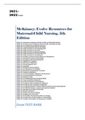
E1.1 A microprocessor controlled laser system:
67 67 67 67
Error Current i(t) 67
Desired Power
6 powe 7 - out
r
6 outp 7
ut Measured
6 7 power
E1.2 A driver controlled cruise control system:
67 67 67 67 67
Controller
Foot pedal
Desired
67
Car and67
Actual
Driver
6
d
spee 7 - Engin
67
auto
6 speed
7
Measurement e
Speedometer
Visual indication of speed
67 67
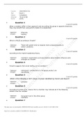
E1.3 6 7 Although the principle of conservation of momentum explains
6 7 6 7 6 7 6 7 6 7 6 7 6 7 6 7
6 7 much of the process of fly-casting, there does not exist a comprehensive
6 7 67 67 67 67 67 67 67 67 67 67
67scientific explanation of how a fly-fisher uses the small backward and
67 67 67 67 67 67 67 67 67 67
67forward mo- tion of the fly rod to cast an almost weightless fly
67 6 7 6 7 6 7 6 7 6 7 6 7 6 7 6 7 6 7 6 7 6 7
6 7lure long distances (the
6 7 6 7 6 7
1
, 2 CHAPTER 1 67 6 7 6 7 Introduction to Control Systems 67 67 67
current world-record is 236 ft). The fly lure is attached to a short invisible
67 67 67 67 67 67 67 67 67 67 67 67 67
leader about 15-ft long, which is in turn attached to a longer and thicker
67 67 67 67 67 67 67 67 67 67 67 67 67 67
Dacron line. The objective is cast the fly lure to a distant spot with dead-
67 67 67 67 67 67 67 67 67 67 67 67 67 67 67
eye accuracy so that the thicker part of the line touches the water first
67 67 67 67 67 67 67 67 67 67 67 67 67 67
and then the fly gently settles on the water just as an insect might.
67 67 67 67 67 67 67 67 67 67 67 67 67 67
Wind
Controller
Mind and 67
Actual
of - body of
67 67 6 positi
7
67 67
on of
fly the fly-
67 67
67 cast the fly
67
6
67
7
fisher
Measurement
67 of
Visual indication
67
67
6 of the
7 67
position of
67 67
the fly
E1.4 An autofocus camera control system:
67 67 67 67
One-way trip time for the beam
67 67 67 67 67
Conversion factor 67
67 1 6 (speed of light
7 67 67
or
67
sound)
Emitter/
Distance to subject 67 67
6 7
Lens
67 67 67 67 67
14th Global Edition By Richard C. Dorf
67 67 67 67 67 67
Chapters 1 - 13, Complete
67 67 67 67
,T A B L
6 7 6 7 6 7 6 7 6 7 6 7 6 7 E 6 7 6 7 - O F
6 7 6 7 6 7 6 7 6 7 - 6 7 6 7 C 6 7 O N 6 7 6 7 6 7 6 7 T E 6 7 6 7 6 7
N T S
6 7 6 7 6 7 6 7
1. Introduction to Control Systems........................................................... 1
67 67 67
2. Mathematical Models of Systems ..................................................... 206 7 6 7 6 7
3. State Variable Models ....................................................................... 79
6 7 6 7
4. Feedback Control System Characteristics .......................................... 126
67 67 67
5. The Performance of Feedback Control Systems ........................ 166
6 7 6 7 6 7 6 7 6 7
6. The Stability of Linear Feedback Systems .............................. 216
6 7 6 7 6 7 6 7 6 7
7. The Root Locus Method .............................................................. 257
6 7 6 7 6 7
8. Frequency Response Methods.......................................................... 359
6 7 6 7
9. Stability in the Frequency Domain ............................................. 420
6 7 6 7 6 7 6 7
10. The Design of Feedback Control Systems................................. 492
6 7 6 7 6 7 6 7 6 7
11. The Design of State Variable Feedback Systems .................... 574
6 7 6 7 6 7 6 7 6 7 6 7
12. Robust Control Systems .................................................................... 633
67 67
13. Digital Control Systems .................................................................... 691
6 7 6 7
, C 6 7 6 7 H 6 7 A 6 7 P T 6 7 6 7 6 7 E R 6 7 6 7
1
Introduction to Control Systems 6 7 6 7 6 7
There are, in general, no unique solutions to the following exercises and
67 67 67 67 67 67 67 67 67 67 67
problems. Other equally valid block diagrams may be submitted by the
67 67 67 67 67 67 67 67 67 67 67
student.
67
Exercises
E1.1 A microprocessor controlled laser system:
67 67 67 67
Error Current i(t) 67
Desired Power
6 powe 7 - out
r
6 outp 7
ut Measured
6 7 power
E1.2 A driver controlled cruise control system:
67 67 67 67 67
Controller
Foot pedal
Desired
67
Car and67
Actual
Driver
6
d
spee 7 - Engin
67
auto
6 speed
7
Measurement e
Speedometer
Visual indication of speed
67 67
E1.3 6 7 Although the principle of conservation of momentum explains
6 7 6 7 6 7 6 7 6 7 6 7 6 7 6 7
6 7 much of the process of fly-casting, there does not exist a comprehensive
6 7 67 67 67 67 67 67 67 67 67 67
67scientific explanation of how a fly-fisher uses the small backward and
67 67 67 67 67 67 67 67 67 67
67forward mo- tion of the fly rod to cast an almost weightless fly
67 6 7 6 7 6 7 6 7 6 7 6 7 6 7 6 7 6 7 6 7 6 7
6 7lure long distances (the
6 7 6 7 6 7
1
, 2 CHAPTER 1 67 6 7 6 7 Introduction to Control Systems 67 67 67
current world-record is 236 ft). The fly lure is attached to a short invisible
67 67 67 67 67 67 67 67 67 67 67 67 67
leader about 15-ft long, which is in turn attached to a longer and thicker
67 67 67 67 67 67 67 67 67 67 67 67 67 67
Dacron line. The objective is cast the fly lure to a distant spot with dead-
67 67 67 67 67 67 67 67 67 67 67 67 67 67 67
eye accuracy so that the thicker part of the line touches the water first
67 67 67 67 67 67 67 67 67 67 67 67 67 67
and then the fly gently settles on the water just as an insect might.
67 67 67 67 67 67 67 67 67 67 67 67 67 67
Wind
Controller
Mind and 67
Actual
of - body of
67 67 6 positi
7
67 67
on of
fly the fly-
67 67
67 cast the fly
67
6
67
7
fisher
Measurement
67 of
Visual indication
67
67
6 of the
7 67
position of
67 67
the fly
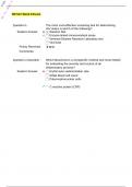
E1.4 An autofocus camera control system:
67 67 67 67
One-way trip time for the beam
67 67 67 67 67
Conversion factor 67
67 1 6 (speed of light
7 67 67
or
67
sound)
Emitter/
Distance to subject 67 67
6 7
Lens