@PROFDOCDIGITALLIBRARIES
Radio Frequency Integrated
Circuits and Systems 2nd
Edition
Solution Manual
BY
JN
Hooman Darabi
U
R
SE
,@PROFDOCDIGITALLIBRARIES
Solutions to Problem Sets
The selected solutions to all 12 chapters problem sets are presented in this manual. The problem
sets depict examples of practical applications of the concepts described in the book, more
detailed analysis of some of the ideas, or in some cases present a new concept.
Note that selected problems have been given answers already in the book.
JN
U
R
SE
,@PROFDOCDIGITALLIBRARIES
1 Chapter One
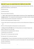
1. Using spherical coordinates, find the capacitance formed by two concentric spherical
conducting shells of radius a, and b. What is the capacitance of a metallic marble with a
diameter of 1cm in free space? Hint: let 𝑏 → ∞, thus, 𝐶 = 4𝜋𝜀𝜀0 𝑎 = 0.55𝑝𝐹.
Solution: Suppose the inner sphere has a surface charge density of +𝜌𝑆. The outer surface
charge density is negative, and proportionally smaller (by (𝑎/𝑏)2) to keep the total charge
the same.
-
+
+S - + a + -
JN
b
+
-
U
From Gauss’s law:
�𝐷 ⋅ 𝑑𝑺𝑺 = 𝑄𝑄 = +𝜌𝑆4𝜋𝑎2
R
𝑆
Thus, inside the sphere (𝑎 ≤ 𝑟 ≤ 𝑏):
𝑎2
SE
𝐷 = 𝜌𝑆
𝑎𝑟
𝑟2
Assuming a potential of 𝑉0 between the inner and outer surfaces, we have:
𝑎 2 1 1
𝑉0 = − � 1 𝜌𝑆 𝑎 𝑑𝑟 = 𝜌𝑆 𝑎2( − )
𝑏 𝜖𝜖 𝑟2 𝜖𝜖 𝑎 𝑏
Thus:
𝑄𝑄 𝜌𝑆4𝜋𝑎2
𝐶=𝑉 = = 4𝜋𝜖𝜖
𝜌𝑆 2 1 1 1 1
𝑎−𝑏
0 𝑎 ( − )
𝜖𝜖 𝑎 𝑏
1
In the case of a metallic marble, 𝑏 → ∞, and hence: 𝐶 = 4𝜋𝜀𝜀0 𝑎. Letting 𝜀𝜀0 = ×
36𝜋
10−9, and 𝑎 = 0.5𝑐𝑚, it yields 𝐶 = 5 𝑝𝐹 = 0.55𝑝𝐹.
9
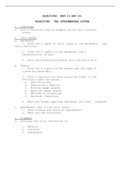
2. Consider the parallel plate capacitor containing two different dielectrics. Find the total
capacitance as a function of the parameters shown in the figure.
, @PROFDOCDIGITALLIBRARIES
Area: A
1
d1
2
d2
Solution: Since in the boundary no charge exists (perfect insulator), the normal component
of the electric flux density has to be equal in each dielectric. That is:
𝐷𝟏𝟏 = 𝐷𝟐𝟐
Accordingly:
JN
𝜖𝜖1 𝐸𝟏𝟏 = 𝜖𝜖2 𝐸𝟐𝟐
Assuming a surface charge density of +𝜌𝑆 for the top plate, and −𝜌𝑆 for the bottom plate, the
electric field (or flux has a component only in z direction, and we have:
U
𝐷𝟏𝟏 = 𝐷𝟐𝟐 = −𝜌𝑆 𝑎𝒛𝒛
If the potential between the top ad bottom plates is 𝑉0, based on the line integral we obtain:
R
𝑑1+𝑑2 𝑑2
−𝜌𝑆 𝑑1+𝑑2 −𝜌
𝑆 𝜌𝑆 𝜌𝑆
𝑉0 = − � 𝐸. 𝑑𝒛𝒛 = − � 𝜖𝜖 𝑑𝑧 − � 𝜖𝜖 𝑑𝑧 = 𝜖𝜖 𝑑1 + 𝜖𝜖 𝑑2
SE
0 0 2 𝑑2 1 1 2
Since the total charge on each plate is: 𝑄𝑄 = 𝜌𝑆𝐴, the capacitance is found to be:
𝑄𝑄 𝐴
𝐶=𝑉 =𝑑 𝑑
0 1 2
𝜖𝜖1 + 𝜖𝜖2
which is analogous to two parallel capacitors.
3. What would be the capacitance of the structure in problem 2 if there were a third conductor
with zero thickness at the interface of the dielectrics? How would the electric field lines
look? How does the capacitance change if the spacing between the top and bottom plates are
kept the same, but the conductor thickness is not zero?
Radio Frequency Integrated
Circuits and Systems 2nd
Edition
Solution Manual
BY
JN
Hooman Darabi
U
R
SE
,@PROFDOCDIGITALLIBRARIES
Solutions to Problem Sets
The selected solutions to all 12 chapters problem sets are presented in this manual. The problem
sets depict examples of practical applications of the concepts described in the book, more
detailed analysis of some of the ideas, or in some cases present a new concept.
Note that selected problems have been given answers already in the book.
JN
U
R
SE
,@PROFDOCDIGITALLIBRARIES
1 Chapter One
1. Using spherical coordinates, find the capacitance formed by two concentric spherical
conducting shells of radius a, and b. What is the capacitance of a metallic marble with a
diameter of 1cm in free space? Hint: let 𝑏 → ∞, thus, 𝐶 = 4𝜋𝜀𝜀0 𝑎 = 0.55𝑝𝐹.
Solution: Suppose the inner sphere has a surface charge density of +𝜌𝑆. The outer surface
charge density is negative, and proportionally smaller (by (𝑎/𝑏)2) to keep the total charge
the same.
-
+
+S - + a + -
JN
b
+
-
U
From Gauss’s law:
�𝐷 ⋅ 𝑑𝑺𝑺 = 𝑄𝑄 = +𝜌𝑆4𝜋𝑎2
R
𝑆
Thus, inside the sphere (𝑎 ≤ 𝑟 ≤ 𝑏):
𝑎2
SE
𝐷 = 𝜌𝑆
𝑎𝑟
𝑟2
Assuming a potential of 𝑉0 between the inner and outer surfaces, we have:
𝑎 2 1 1
𝑉0 = − � 1 𝜌𝑆 𝑎 𝑑𝑟 = 𝜌𝑆 𝑎2( − )
𝑏 𝜖𝜖 𝑟2 𝜖𝜖 𝑎 𝑏
Thus:
𝑄𝑄 𝜌𝑆4𝜋𝑎2
𝐶=𝑉 = = 4𝜋𝜖𝜖
𝜌𝑆 2 1 1 1 1
𝑎−𝑏
0 𝑎 ( − )
𝜖𝜖 𝑎 𝑏
1
In the case of a metallic marble, 𝑏 → ∞, and hence: 𝐶 = 4𝜋𝜀𝜀0 𝑎. Letting 𝜀𝜀0 = ×
36𝜋
10−9, and 𝑎 = 0.5𝑐𝑚, it yields 𝐶 = 5 𝑝𝐹 = 0.55𝑝𝐹.
9
2. Consider the parallel plate capacitor containing two different dielectrics. Find the total
capacitance as a function of the parameters shown in the figure.
, @PROFDOCDIGITALLIBRARIES
Area: A
1
d1
2
d2
Solution: Since in the boundary no charge exists (perfect insulator), the normal component
of the electric flux density has to be equal in each dielectric. That is:
𝐷𝟏𝟏 = 𝐷𝟐𝟐
Accordingly:
JN
𝜖𝜖1 𝐸𝟏𝟏 = 𝜖𝜖2 𝐸𝟐𝟐
Assuming a surface charge density of +𝜌𝑆 for the top plate, and −𝜌𝑆 for the bottom plate, the
electric field (or flux has a component only in z direction, and we have:
U
𝐷𝟏𝟏 = 𝐷𝟐𝟐 = −𝜌𝑆 𝑎𝒛𝒛
If the potential between the top ad bottom plates is 𝑉0, based on the line integral we obtain:
R
𝑑1+𝑑2 𝑑2
−𝜌𝑆 𝑑1+𝑑2 −𝜌
𝑆 𝜌𝑆 𝜌𝑆
𝑉0 = − � 𝐸. 𝑑𝒛𝒛 = − � 𝜖𝜖 𝑑𝑧 − � 𝜖𝜖 𝑑𝑧 = 𝜖𝜖 𝑑1 + 𝜖𝜖 𝑑2
SE
0 0 2 𝑑2 1 1 2
Since the total charge on each plate is: 𝑄𝑄 = 𝜌𝑆𝐴, the capacitance is found to be:
𝑄𝑄 𝐴
𝐶=𝑉 =𝑑 𝑑
0 1 2
𝜖𝜖1 + 𝜖𝜖2
which is analogous to two parallel capacitors.
3. What would be the capacitance of the structure in problem 2 if there were a third conductor
with zero thickness at the interface of the dielectrics? How would the electric field lines
look? How does the capacitance change if the spacing between the top and bottom plates are
kept the same, but the conductor thickness is not zero?