School of Engineering Technology
EET230
Digital Systems II
Lab 2 – Frequency Dividers
Objectives
Investigate the operation of various configurations of Flip-Flops
Introduction
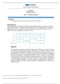
Another application of a flip-flop is dividing (reducing) the frequency of a periodic waveform.
When a pulse waveform is applied to the clock input of a D or J-K flip-flop that is connected to
toggle, the Q output is a square wave with one-half the frequency of the clock input. Thus, a
single flip-flop can be applied as a divide-by-2 device.
Abstract
This laboratory experiment examines the application of flip-flops as frequency dividers,
illustrating how sequential logic can reduce the frequency of a periodic waveform. A circuit
was designed and simulated in Multisim using JK flip-flops configured to function as
divide-by-2 devices. When a clock signal was applied to the input, the Q output toggled at
half the clock frequency, confirming the frequency division. A frequency counter (XFC)
was employed to measure and validate the output frequencies at each stage. Furthermore, a
7-segment display was integrated to visualize the binary counting sequence resulting from
cascading multiple flip-flops. The results confirm the effectiveness of flip-flops in
frequency division and digital counting applications, highlighting their significance in
digital electronics.
This study source was downloaded by 100000901878207 from CourseHero.com1 on 10-31-2025 14:51:19 GMT -05:00
https://www.coursehero.com/file/248843138/W1-Flip-Flops-Lab-Lab-2docx/
, School of Engineering Technology
Parts List
Miscellaneous: Components Measuring Instruments:
1. SN74LS76 Dual JK Flip Flop Frequency Counter
Multisim© Software Logic Probe
7-Segment Display
Refer to the ICs (integrated circuits) datasheets in your course shell for a complete understanding of
their characteristics.
Circuit Construction:
Download and open the Multisim file for Lab 2 from your course shell.
The Multisim file includes all parts of the lab with all needed components.
Procedures:
1. Connect your circuit as shown below.
2. Connect each ‘Frequency Counter’ (XFC) to the output Q’ of each flip-flop as shown
above
3. Double Click each ‘Frequency Counter (XFC)’ and make sure it is set as follows
This study source was downloaded by 100000901878207 from CourseHero.com2 on 10-31-2025 14:51:19 GMT -05:00
https://www.coursehero.com/file/248843138/W1-Flip-Flops-Lab-Lab-2docx/
EET230
Digital Systems II
Lab 2 – Frequency Dividers
Objectives
Investigate the operation of various configurations of Flip-Flops
Introduction
Another application of a flip-flop is dividing (reducing) the frequency of a periodic waveform.
When a pulse waveform is applied to the clock input of a D or J-K flip-flop that is connected to
toggle, the Q output is a square wave with one-half the frequency of the clock input. Thus, a
single flip-flop can be applied as a divide-by-2 device.
Abstract
This laboratory experiment examines the application of flip-flops as frequency dividers,
illustrating how sequential logic can reduce the frequency of a periodic waveform. A circuit
was designed and simulated in Multisim using JK flip-flops configured to function as
divide-by-2 devices. When a clock signal was applied to the input, the Q output toggled at
half the clock frequency, confirming the frequency division. A frequency counter (XFC)
was employed to measure and validate the output frequencies at each stage. Furthermore, a
7-segment display was integrated to visualize the binary counting sequence resulting from
cascading multiple flip-flops. The results confirm the effectiveness of flip-flops in
frequency division and digital counting applications, highlighting their significance in
digital electronics.
This study source was downloaded by 100000901878207 from CourseHero.com1 on 10-31-2025 14:51:19 GMT -05:00
https://www.coursehero.com/file/248843138/W1-Flip-Flops-Lab-Lab-2docx/
, School of Engineering Technology
Parts List
Miscellaneous: Components Measuring Instruments:
1. SN74LS76 Dual JK Flip Flop Frequency Counter
Multisim© Software Logic Probe
7-Segment Display
Refer to the ICs (integrated circuits) datasheets in your course shell for a complete understanding of
their characteristics.
Circuit Construction:
Download and open the Multisim file for Lab 2 from your course shell.
The Multisim file includes all parts of the lab with all needed components.
Procedures:
1. Connect your circuit as shown below.
2. Connect each ‘Frequency Counter’ (XFC) to the output Q’ of each flip-flop as shown
above
3. Double Click each ‘Frequency Counter (XFC)’ and make sure it is set as follows
This study source was downloaded by 100000901878207 from CourseHero.com2 on 10-31-2025 14:51:19 GMT -05:00
https://www.coursehero.com/file/248843138/W1-Flip-Flops-Lab-Lab-2docx/