All 12 Chapters Covered
SOLUTIONS
,2 Fracture Mechanics: Fundamentals and Applications
CHAPTER 1
1.2 A flat plate with a through-thickness crack (Fig. 1.8) is subject to a 100 MPa (14.5 ksi)
tensile stress and has a fracture toughness (KIc) of 50.0 MPa m (45. ksi in ). Determine
the critical crack length for this plate, assuming the material is linear elastic.
Ans:
At fracture, K Ic K I ac . Therefore,
50 MPa m = 100 MPa ac
ac = 0.0796 m = 79.6 mm
Total crack length = 2ac = 159 mm
1.3 Compute the critical energy release rate (Gc) of the material in the previous problem for E =
207,000 MPa (30,000 ksi)..
Ans:
50 MPa m
2
K Ic
Gc 0.0121 MPa mm 12.1 kPa m
E 207,000 MPa
12.1 kJ/m 2
Note that energy release rate has units of energy/area.
1.4 Suppose that you plan to drop a bomb out of an airplane and that you are interested in the
time of flight before it hits the ground, but you cannot remember the appropriate equation
from your undergraduate physics course. You decide to infer a relationship for time of flight
of a falling object by experimentation. You reason that the time of flight, t, must depend on
the height above the ground, h, and the weight of the object, mg, where m is the mass and g
is the gravitational acceleration. Therefore, neglecting aerodynamic drag, the time of flight
is given by the following function:
t f (h, m, g )
Apply dimensional analysis to this equation and determine how many experiments would
be required to determine the function f to a reasonable approximation, assuming you know
the numerical value of g. Does the time of flight depend on the mass of the object?
@Seismicisolation
@Seismicisolation
,Solutions Manual 3
Ans:
Since h has units of length and g has units of (length)(time)-2, let us divide both
sides of the above equation by h g :
t f h, m, g
h g h g
The left side of this equation is now dimensionless. Therefore, the right side must
also be dimensionless, which implies that the time of flight cannot depend on the
mass of the object. Thus dimensional analysis implies the following functional
relationship:
h
t
g
where is a dimensionless constant. Only one experiment would be required to
estimate , but several trials at various heights might be advisable to obtain a
reliable estimate of this constant. Note that 2 according to Newton's laws of
motion.
CHAPTER 2
2.1 According to Eq. (2.25), the energy required to increase the crack area a unit amount is equal
to twice the fracture work per unit surface area, wf. Why is the factor of 2 in this equation
necessary?
Ans:
The factor of 2 stems from the difference between crack area and surface area.
The former is defined as the projected area of the crack. The surface area is twice
the crack area because the formation of a crack results in the creation of two
surfaces. Consequently, the material resistance to crack extension = 2 wf.
2.2 Derive Eq. (2.30) for both load control and displacement control by substituting Eq. (2.29)
into Eqs. (2.27) and (2.28), respectively.
Ans:
(a) Load control.
P d P d CP P dC
G
2 B da P 2 B da P 2 B da
@Seismicisolation
@Seismicisolation
,4 Fracture Mechanics: Fundamentals and Applications
(b) Displacement control.
dP
G
2B da
dP d 1
C dC
da da C 2 da
2
dC P 2 dC
G C
2B da 2 B da
2.3 Figure 2.10 illustrates that the driving force is linear for a through-thickness crack in an
infinite plate when the stress is fixed. Suppose that a remote displacement (rather than load)
were fixed in this configuration. Would the driving force curves be altered? Explain. (Hint:
see Section 2.5.3).
Ans:
In a cracked plate where 2a << the plate width, crack extension at a fixed remote
displacement would not effect the load, since the crack comprises a negligible
portion of the cross section. Thus a fixed remote displacement implies a fixed load,
and load control and displacement control are equivalent in this case. The driving
force curves would not be altered if remote displacement, rather than stress, were
specified.
Consider the spring in series analog in Fig. 2.12. The load and remote
displacement are related as follows:
T = (C + Cm) P T C Cm P
where C is the “local” compliance and Cm is the system compliance. For the present
problem, assume that Cm represents the compliance of the uncracked plate and C is
the additional compliance that results from the presence of the crack. When the
crack is small compared to the plate dimensions, Cm >> C. If the crack were to
grow at a fixed T, only C would change; thus load would also remain fixed.
2.4 A plate 2W wide contains a centrally located crack 2a long and is subject to a tensile load,
P. Beginning with Eq. (2.24), derive an expression for the elastic compliance, C (= /P) in
terms of the plate dimensions and elastic modulus, E. The stress in Eq. (2.24) is the nominal
value; i.e., = P/2BW in this problem. (Note: Eq. (2.24) only applies when a << W; the
expression you derive is only approximate for a finite width plate.)
@Seismicisolation
@Seismicisolation
,Solutions Manual 5
Ans:
The through-thickness crack has two tips; an increment of crack growth causes the
crack area to increase by 2B da. The compliance relationship for energy release
rate must be modified accordingly:
P 2 dC P 2 dC
G
2 B d 2a 4 B da
Equating the above expression with Eq. (2.24) gives
2 a P 2 a P 2 dC
G
E 4 B 2W 2 E 4 B da
Solving for compliance leads to
a
2
C dC ada constant
2
BW E BE W
The constant corresponds to the compliance of the uncracked plate. Assuming a
gage length L, the total compliance is given by
a L 1
2 2
Ctot C Cm
BE W 2BWE
where Cm represents the compliance of the uncracked plate and C is the additional
compliance due to the crack. When a << W or a << L, the first term in the above
expression is negligible. Recall the previous problem, where it was argued that
displacement control is equivalent to load control in an infinite plate because C <<
Cm.
2.5 A material exhibits the following crack growth resistance behavior:
R 6.95(a ao )0.5
where ao is the initial crack size. R has units of kJ/m2 and crack size is in millimeters.
Alternatively,
R 200( a ao ) 0.5
where R has units of in-lb/in2 and crack size is in inches. The elastic modulus of this material
= 207,000 MPa (30,000 ksi). Consider a wide plate with a through crack (a << W) that is
made from this material.
@Seismicisolation
@Seismicisolation
,6 Fracture Mechanics: Fundamentals and Applications
(a) If this plate fractures at 138 MPa (20.0 ksi), compute the following:
(i) The half crack size at failure (ac).
(ii) The amount of stable crack growth (at each crack tip) that precedes failure
(ac - ao).
(b) If this plate has an initial crack length (2ao) of 50.8 mm (2.0 in)
and the plate is loaded to failure, compute the following:
(i) The stress at failure.
(ii) The half crack size at failure.
(iii) The stable crack growth at each crack tip
Ans:
At instability, G = R and dG/da = dR/da. Therefore,
2 ac
6.95 ac ao
0.5
(1)
E
and
2
3.48 ac ao
0.5
(2)
E
Thus we have two equations to relate , ac and ao, and we must specify one of these
quantities.
(a) = 138 MPa
From Eq. (1) above,
138, 000 kPa
2
3.48 ac ao
0.5
2.07 10 kPa
8
ac - ao = 145 mm
Substituting into (2) gives
138, 000 kPa ac
2
6.95 145 mm
0.5
2.07 10 kPa
8
Thus
(i) ac = 290 mm
(ii) ac - ao = 145 mm
(iii) ao = 145 mm
@Seismicisolation
@Seismicisolation
,Solutions Manual 7
(b) ao = 25.4 mm
Dividing Eq. (1) by Eq. (2) leads to
ac 2 ac ao
Therefore, if ao = 25.4 mm, ac = 50.8 mm and (ac - ao) = 25.4 mm. We can solve
for critical stress by substituting these results into Eq. (1):
2 0.0508 m
6.95 25.4 mm
0.5
2.07 10 kPa
8
Thus
(i) = 213,000 kPa = 213 MPa
(ii) ac = 50.8 mm
(iii) ac - ao = 25.4 mm
2.6 Suppose that a double cantilever beam specimen (Fig. 2.9) is fabricated from the same
material considered in Problem 2.5. Calculate the load at failure and the amount of stable
crack growth. The specimen dimensions are as follows:
B = 25.4 mm (1 in) h = 12.7 mm (0.5 in) ao = 152 mm (6 in)
Ans:
At instability, G = R and dG/da = dR/da. Hence,
12 Pc 2 ac 2
Gc 2 3 6.95 ac ao
0.5
(1)
BhE
2Gc
3.48 ac ao
0.5
(2)
a
Dividing (1) by (2) gives
ac
2 ac ao
2
Thus
4
ac ao 203 mm
3
and
@Seismicisolation
@Seismicisolation
,8 Fracture Mechanics: Fundamentals and Applications
12 Pc 2 0.203 m
2
Gc 6.95 203 152
0.5
0.025 m 0.0127 m 2.07 10 kPa
2 3 8
Pc = 5.16 kN
2.7 Consider a nominally linear elastic material with a rising R curve (e.g., Problems 2.5 and
2.6). Suppose that one test is performed on wide plate with a through crack (Fig. 2.3) and a
second test on the same material is performed on a DCB specimen (Fig. 2.9). If both tests
are conducted in load control, would the Gc values at instability be the same? If not, which
geometry would result in a higher Gc? Explain.
Ans
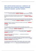
The driving force curve for the through crack is linear, while G varies with a2 for
the DCB specimen. Therefore, the two geometries would have different points of
tangency on the R curve, as Fig. S1 illustrates. The Gcvalue for the through crack
would be higher, and this geometry would experience more stable crack growth
prior to failure.
Through
Crack
DCB
G, R Specimen
Gc(1) R
Gc(2)
Crack Size
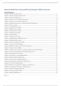
FIGURE S1 Effect of specimen geometry on instability (Problem 2.7)
2.8 Example 2.3 showed that the energy release rate, G, of the double cantilever beam (DCB)
specimen increases with crack growth when the specimen is held at a constant load.
Describe (qualitatively) how you could alter the design of the DCB specimen such that a
growing crack in load control would experience a constant G.
@Seismicisolation
@Seismicisolation
,Solutions Manual 9
Ans:
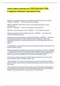
In a conventional DCB specimen, compliance varies with a3, and energy release is
proportional to a2 when load is fixed. In order for G to remain constant with crack
growth, compliance must vary linearly with crack length. One way to accomplish
this is to taper the specimen width, as Fig. S2 illustrates. Alternatively, the
thickness can be tapered. The latter method is not as effective as the former because
compliance is less sensitive to the thickness dimension; recall that the moment of
inertia of the cross section is proportional to Bh3. Specimens such as illustrated in
Fig. S2, where G is relatively constant over a range of crack lengths, have been used
successfully in laboratory experiments.
FIGURE S2 Tapered DCB specimen
(Problem 2.8).
2.9 Beginning with Eq. (2.20), derive an expression for the potential energy of a plate subject
to a tensile stress with a penny-shaped flaw of radius a. Assume that a << plate
dimensions.
Ans:
At fracture,
d dWS
d d
For the penny-shaped crack,
WS 2 s a 2
and
dWS
2 s
d
Combining the above results with Eq. (2.20) gives
@Seismicisolation
@Seismicisolation
, 10 Fracture Mechanics: Fundamentals and Applications
4 1 2 a f 2 d
2 s
E d
The above equation must be integrated with respect to crack area to infer the
potential energy. The crack area can be written in terms of the the crack radius, a:
dA 2 ada
and
d 1 d
dA 2 a da
Therefore,
d 8 2 a 2 1 2
da E
and
8 2 a3 1 2
o
3E
where o is the potential energy of the uncracked solid.
2.10 Beginning with Eq. (2.20), derive expressions for the energy release rate and Mode I stress
intensity factor of a penny-shaped flaw subject to a remote tensile stress. (Your KI
expression should be identical to Eq. (2.44).)
Ans:
At fracture in an ideally brittle material, G Gc 2 s . Rearranging Eq. (2.20) leads
to
4 1 2 a f 2
2 s Gc
E
Thus
4 1 2 a 2 4(1 - 2) a 2
G G =
E E
Invoking the relationship between KI and G (Eq. (2.56)) gives
2
KI a
@Seismicisolation
@Seismicisolation
SOLUTIONS
,2 Fracture Mechanics: Fundamentals and Applications
CHAPTER 1
1.2 A flat plate with a through-thickness crack (Fig. 1.8) is subject to a 100 MPa (14.5 ksi)
tensile stress and has a fracture toughness (KIc) of 50.0 MPa m (45. ksi in ). Determine
the critical crack length for this plate, assuming the material is linear elastic.
Ans:
At fracture, K Ic K I ac . Therefore,
50 MPa m = 100 MPa ac
ac = 0.0796 m = 79.6 mm
Total crack length = 2ac = 159 mm
1.3 Compute the critical energy release rate (Gc) of the material in the previous problem for E =
207,000 MPa (30,000 ksi)..
Ans:
50 MPa m
2
K Ic
Gc 0.0121 MPa mm 12.1 kPa m
E 207,000 MPa
12.1 kJ/m 2
Note that energy release rate has units of energy/area.
1.4 Suppose that you plan to drop a bomb out of an airplane and that you are interested in the
time of flight before it hits the ground, but you cannot remember the appropriate equation
from your undergraduate physics course. You decide to infer a relationship for time of flight
of a falling object by experimentation. You reason that the time of flight, t, must depend on
the height above the ground, h, and the weight of the object, mg, where m is the mass and g
is the gravitational acceleration. Therefore, neglecting aerodynamic drag, the time of flight
is given by the following function:
t f (h, m, g )
Apply dimensional analysis to this equation and determine how many experiments would
be required to determine the function f to a reasonable approximation, assuming you know
the numerical value of g. Does the time of flight depend on the mass of the object?
@Seismicisolation
@Seismicisolation
,Solutions Manual 3
Ans:
Since h has units of length and g has units of (length)(time)-2, let us divide both
sides of the above equation by h g :
t f h, m, g
h g h g
The left side of this equation is now dimensionless. Therefore, the right side must
also be dimensionless, which implies that the time of flight cannot depend on the
mass of the object. Thus dimensional analysis implies the following functional
relationship:
h
t
g
where is a dimensionless constant. Only one experiment would be required to
estimate , but several trials at various heights might be advisable to obtain a
reliable estimate of this constant. Note that 2 according to Newton's laws of
motion.
CHAPTER 2
2.1 According to Eq. (2.25), the energy required to increase the crack area a unit amount is equal
to twice the fracture work per unit surface area, wf. Why is the factor of 2 in this equation
necessary?
Ans:
The factor of 2 stems from the difference between crack area and surface area.
The former is defined as the projected area of the crack. The surface area is twice
the crack area because the formation of a crack results in the creation of two
surfaces. Consequently, the material resistance to crack extension = 2 wf.
2.2 Derive Eq. (2.30) for both load control and displacement control by substituting Eq. (2.29)
into Eqs. (2.27) and (2.28), respectively.
Ans:
(a) Load control.
P d P d CP P dC
G
2 B da P 2 B da P 2 B da
@Seismicisolation
@Seismicisolation
,4 Fracture Mechanics: Fundamentals and Applications
(b) Displacement control.
dP
G
2B da
dP d 1
C dC
da da C 2 da
2
dC P 2 dC
G C
2B da 2 B da
2.3 Figure 2.10 illustrates that the driving force is linear for a through-thickness crack in an
infinite plate when the stress is fixed. Suppose that a remote displacement (rather than load)
were fixed in this configuration. Would the driving force curves be altered? Explain. (Hint:
see Section 2.5.3).
Ans:
In a cracked plate where 2a << the plate width, crack extension at a fixed remote
displacement would not effect the load, since the crack comprises a negligible
portion of the cross section. Thus a fixed remote displacement implies a fixed load,
and load control and displacement control are equivalent in this case. The driving
force curves would not be altered if remote displacement, rather than stress, were
specified.
Consider the spring in series analog in Fig. 2.12. The load and remote
displacement are related as follows:
T = (C + Cm) P T C Cm P
where C is the “local” compliance and Cm is the system compliance. For the present
problem, assume that Cm represents the compliance of the uncracked plate and C is
the additional compliance that results from the presence of the crack. When the
crack is small compared to the plate dimensions, Cm >> C. If the crack were to
grow at a fixed T, only C would change; thus load would also remain fixed.
2.4 A plate 2W wide contains a centrally located crack 2a long and is subject to a tensile load,
P. Beginning with Eq. (2.24), derive an expression for the elastic compliance, C (= /P) in
terms of the plate dimensions and elastic modulus, E. The stress in Eq. (2.24) is the nominal
value; i.e., = P/2BW in this problem. (Note: Eq. (2.24) only applies when a << W; the
expression you derive is only approximate for a finite width plate.)
@Seismicisolation
@Seismicisolation
,Solutions Manual 5
Ans:
The through-thickness crack has two tips; an increment of crack growth causes the
crack area to increase by 2B da. The compliance relationship for energy release
rate must be modified accordingly:
P 2 dC P 2 dC
G
2 B d 2a 4 B da
Equating the above expression with Eq. (2.24) gives
2 a P 2 a P 2 dC
G
E 4 B 2W 2 E 4 B da
Solving for compliance leads to
a
2
C dC ada constant
2
BW E BE W
The constant corresponds to the compliance of the uncracked plate. Assuming a
gage length L, the total compliance is given by
a L 1
2 2
Ctot C Cm
BE W 2BWE
where Cm represents the compliance of the uncracked plate and C is the additional
compliance due to the crack. When a << W or a << L, the first term in the above
expression is negligible. Recall the previous problem, where it was argued that
displacement control is equivalent to load control in an infinite plate because C <<
Cm.
2.5 A material exhibits the following crack growth resistance behavior:
R 6.95(a ao )0.5
where ao is the initial crack size. R has units of kJ/m2 and crack size is in millimeters.
Alternatively,
R 200( a ao ) 0.5
where R has units of in-lb/in2 and crack size is in inches. The elastic modulus of this material
= 207,000 MPa (30,000 ksi). Consider a wide plate with a through crack (a << W) that is
made from this material.
@Seismicisolation
@Seismicisolation
,6 Fracture Mechanics: Fundamentals and Applications
(a) If this plate fractures at 138 MPa (20.0 ksi), compute the following:
(i) The half crack size at failure (ac).
(ii) The amount of stable crack growth (at each crack tip) that precedes failure
(ac - ao).
(b) If this plate has an initial crack length (2ao) of 50.8 mm (2.0 in)
and the plate is loaded to failure, compute the following:
(i) The stress at failure.
(ii) The half crack size at failure.
(iii) The stable crack growth at each crack tip
Ans:
At instability, G = R and dG/da = dR/da. Therefore,
2 ac
6.95 ac ao
0.5
(1)
E
and
2
3.48 ac ao
0.5
(2)
E
Thus we have two equations to relate , ac and ao, and we must specify one of these
quantities.
(a) = 138 MPa
From Eq. (1) above,
138, 000 kPa
2
3.48 ac ao
0.5
2.07 10 kPa
8
ac - ao = 145 mm
Substituting into (2) gives
138, 000 kPa ac
2
6.95 145 mm
0.5
2.07 10 kPa
8
Thus
(i) ac = 290 mm
(ii) ac - ao = 145 mm
(iii) ao = 145 mm
@Seismicisolation
@Seismicisolation
,Solutions Manual 7
(b) ao = 25.4 mm
Dividing Eq. (1) by Eq. (2) leads to
ac 2 ac ao
Therefore, if ao = 25.4 mm, ac = 50.8 mm and (ac - ao) = 25.4 mm. We can solve
for critical stress by substituting these results into Eq. (1):
2 0.0508 m
6.95 25.4 mm
0.5
2.07 10 kPa
8
Thus
(i) = 213,000 kPa = 213 MPa
(ii) ac = 50.8 mm
(iii) ac - ao = 25.4 mm
2.6 Suppose that a double cantilever beam specimen (Fig. 2.9) is fabricated from the same
material considered in Problem 2.5. Calculate the load at failure and the amount of stable
crack growth. The specimen dimensions are as follows:
B = 25.4 mm (1 in) h = 12.7 mm (0.5 in) ao = 152 mm (6 in)
Ans:
At instability, G = R and dG/da = dR/da. Hence,
12 Pc 2 ac 2
Gc 2 3 6.95 ac ao
0.5
(1)
BhE
2Gc
3.48 ac ao
0.5
(2)
a
Dividing (1) by (2) gives
ac
2 ac ao
2
Thus
4
ac ao 203 mm
3
and
@Seismicisolation
@Seismicisolation
,8 Fracture Mechanics: Fundamentals and Applications
12 Pc 2 0.203 m
2
Gc 6.95 203 152
0.5
0.025 m 0.0127 m 2.07 10 kPa
2 3 8
Pc = 5.16 kN
2.7 Consider a nominally linear elastic material with a rising R curve (e.g., Problems 2.5 and
2.6). Suppose that one test is performed on wide plate with a through crack (Fig. 2.3) and a
second test on the same material is performed on a DCB specimen (Fig. 2.9). If both tests
are conducted in load control, would the Gc values at instability be the same? If not, which
geometry would result in a higher Gc? Explain.
Ans
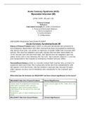
The driving force curve for the through crack is linear, while G varies with a2 for
the DCB specimen. Therefore, the two geometries would have different points of
tangency on the R curve, as Fig. S1 illustrates. The Gcvalue for the through crack
would be higher, and this geometry would experience more stable crack growth
prior to failure.
Through
Crack
DCB
G, R Specimen
Gc(1) R
Gc(2)
Crack Size
FIGURE S1 Effect of specimen geometry on instability (Problem 2.7)
2.8 Example 2.3 showed that the energy release rate, G, of the double cantilever beam (DCB)
specimen increases with crack growth when the specimen is held at a constant load.
Describe (qualitatively) how you could alter the design of the DCB specimen such that a
growing crack in load control would experience a constant G.
@Seismicisolation
@Seismicisolation
,Solutions Manual 9
Ans:
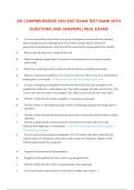
In a conventional DCB specimen, compliance varies with a3, and energy release is
proportional to a2 when load is fixed. In order for G to remain constant with crack
growth, compliance must vary linearly with crack length. One way to accomplish
this is to taper the specimen width, as Fig. S2 illustrates. Alternatively, the
thickness can be tapered. The latter method is not as effective as the former because
compliance is less sensitive to the thickness dimension; recall that the moment of
inertia of the cross section is proportional to Bh3. Specimens such as illustrated in
Fig. S2, where G is relatively constant over a range of crack lengths, have been used
successfully in laboratory experiments.
FIGURE S2 Tapered DCB specimen
(Problem 2.8).
2.9 Beginning with Eq. (2.20), derive an expression for the potential energy of a plate subject
to a tensile stress with a penny-shaped flaw of radius a. Assume that a << plate
dimensions.
Ans:
At fracture,
d dWS
d d
For the penny-shaped crack,
WS 2 s a 2
and
dWS
2 s
d
Combining the above results with Eq. (2.20) gives
@Seismicisolation
@Seismicisolation
, 10 Fracture Mechanics: Fundamentals and Applications
4 1 2 a f 2 d
2 s
E d
The above equation must be integrated with respect to crack area to infer the
potential energy. The crack area can be written in terms of the the crack radius, a:
dA 2 ada
and
d 1 d
dA 2 a da
Therefore,
d 8 2 a 2 1 2
da E
and
8 2 a3 1 2
o
3E
where o is the potential energy of the uncracked solid.
2.10 Beginning with Eq. (2.20), derive expressions for the energy release rate and Mode I stress
intensity factor of a penny-shaped flaw subject to a remote tensile stress. (Your KI
expression should be identical to Eq. (2.44).)
Ans:
At fracture in an ideally brittle material, G Gc 2 s . Rearranging Eq. (2.20) leads
to
4 1 2 a f 2
2 s Gc
E
Thus
4 1 2 a 2 4(1 - 2) a 2
G G =
E E
Invoking the relationship between KI and G (Eq. (2.56)) gives
2
KI a
@Seismicisolation
@Seismicisolation