CHAPTER 2 – LOAD COMBINATIONS
Problem 2.1
SOLUTION
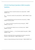
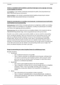
Table P2.1 Strength Design Load Combinations for the Beam in Problem 2.1
Bending Moment, ft-kips (kN-m)
ASCE/SEI
Equation Exterior Interior
Equation No. Positive
Negative Negative
1a 1.4𝐷 –18.6 (–25.2) 61.5 (83.4) –74.5 (–101.0)
2a 1.2𝐷 + 1.6𝐿 –36.6 (–49.6) 120.7 (163.7) –146.4 (–198.5)
3a, 4a 1.2𝐷 + 0.5𝐿 –22.4 (–30.4) 73.9 (100.2) –89.6 (–121.5)
5a 0.9𝐷 –12.0 (–16.3) 39.5 (53.6) –47.9 (–64.9)
3
,Problem 2.2
SOLUTION
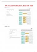
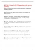
Table P2.2 Strength Design Load Combinations for the Beam in Problem 2.2
ASCE/SEI Bending Moment, ft-kips Shear Force,
Equation Equation (kN-m) kips (kN)
No. Left Support Midspan Left Support
–80.6 57.5 16.5
1a 1.4𝐷
(–109.3) (78.0) (77.4)
–105.1 75.2 21.5
2a 1.2𝐷 + 1.6𝐿
(–142.5) (102.0) (95.6)
–80.4 57.4 16.5
1.2𝐷 + 0.5𝐿
(–109.0) (77.8) (73.4)
–42.1 49.3 11.8
3a SSR
(–57.1) (66.8) (52.5)
1.2𝐷 + 0.5𝑊
–96.1 49.3 16.6
SSL
(–130.3) (66.8) (73.8)
–26.4 57.4 11.7
SSR
(–35.8) (77.8) (52.0)
4a 1.2𝐷 + 1.0𝑊 + 0.5𝐿
–134.4 57.4 21.3
SSL
(–182.2) (77.8) (94.8)
2.2 37.0 5.8
SSR
(3.0) (50.2) (25.8)
5a 0.9𝐷 + 1.0𝑊
–105.8 37.0 15.4
SSL
(–143.5) (50.2) (68.5)
4
,Problem 2.3
SOLUTION
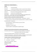
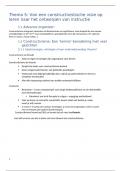
Table P2.3 Allowable Stress Design Load Combinations for the Beam in Problem 2.3
ASCE/SEI Bending Moment, ft-kips Shear Force,
Equation Equation (kN-m) kips (kN)
No. Left Support Midspan Left Support
–57.6 41.1 11.8
1a 𝐷
(–78.1) (55.7) (52.5)
–80.1 57.3 16.4
2a 𝐷+𝐿
(–108.6) (77.7) (73.0)
–74.5 53.3 15.3
4a 𝐷 + 0.75𝐿
(–101.0) (72.3) (68.1)
–25.2 41.1 8.9
SSR
(–34.2) (55.7) (39.6)
5a 𝐷 + 0.6𝑊
–90.0 41.1 14.7
SSL
(–122.0) (55.7) (65.4)
–50.2 53.3 13.1
SSR
𝐷 + 0.75𝐿 (–68.1) (72.3) (58.3)
6a
+ 0.75(0.6𝑊) –98.8 53.3 17.4
SSL
(–134.0) (72.3) (77.4)
–2.2 24.7 4.2
SSR
(–3.0) (33.5) (18.7)
7a 0.6𝐷 + 0.6𝑊
–67.0 24.7 10.0
SSL
(–90.8) (33.5) (44.5)
5
, Problem 2.4
SOLUTION
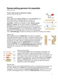
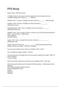
Table P2.4 Alternative Basic Allowable Stress Design Load Combinations for the Beam
in Problem 2.4
IBC Bending Moment, ft-kips Shear Force,
Equation Equation (kN-m) kips (kN)
No. Left Support Midspan Left Support
–80.1 57.3 16.4
16-1 𝐷+𝐿
(–108.6) (77.7) (73.0)
–47.7 57.3 13.5
SSR
(–64.7) (77.7) (60.1)
16-2, 16-3 𝐷 + 𝐿 + 0.6𝑊
–112.5 57.3 19.3
SSL
(–152.5) (77.7) (85.8)
–63.9 57.3 15.0
SSR
(–86.6) (77.7) (66.6)
16-4 𝐷 + 𝐿 + 0.6𝑊 ⁄2
–96.3 57.3 17.8
SSL
(–130.6) (77.7) (79.4)
Problem 2.5
SOLUTION
Because the live loads on the floors are equal to 100 lb/ft2 (4.79 kN/m2), the load factor
on 𝐿 is permitted to be taken as 0.5.
The seismic load effect, 𝐸, is determined as follows:
• For use in ASCE/SEI Equation 6:
𝐸 = 𝐸ℎ + 𝐸𝑣 = 𝜌𝑄𝐸 + 0.2𝑆𝐷𝑆 𝐷 = (1.0 × 𝑄𝐸 ) + (0.2 × 0.41 × 𝐷) = 𝑄𝐸 + 0.08𝐷
• For use in ASCE/SEI Equation 7:
𝐸 = 𝐸ℎ − 𝐸𝑣 = 𝜌𝑄𝐸 − 0.2𝑆𝐷𝑆 𝐷 = (1.0 × 𝑄𝐸 ) − (0.2 × 0.41 × 𝐷) = 𝑄𝐸 − 0.08𝐷
Substituting for 𝐸, ASCE/SEI Equation 6 becomes the following:
1.2𝐷 + 𝑄𝐸 + 0.08𝐷 + 0.5𝐿 + 0.15𝑆 = 1.28𝐷 + 𝑄𝐸 + 0.5𝐿
Similarly, ASCE/SEI Equation 7 becomes the following:
6
Problem 2.1
SOLUTION
Table P2.1 Strength Design Load Combinations for the Beam in Problem 2.1
Bending Moment, ft-kips (kN-m)
ASCE/SEI
Equation Exterior Interior
Equation No. Positive
Negative Negative
1a 1.4𝐷 –18.6 (–25.2) 61.5 (83.4) –74.5 (–101.0)
2a 1.2𝐷 + 1.6𝐿 –36.6 (–49.6) 120.7 (163.7) –146.4 (–198.5)
3a, 4a 1.2𝐷 + 0.5𝐿 –22.4 (–30.4) 73.9 (100.2) –89.6 (–121.5)
5a 0.9𝐷 –12.0 (–16.3) 39.5 (53.6) –47.9 (–64.9)
3
,Problem 2.2
SOLUTION
Table P2.2 Strength Design Load Combinations for the Beam in Problem 2.2
ASCE/SEI Bending Moment, ft-kips Shear Force,
Equation Equation (kN-m) kips (kN)
No. Left Support Midspan Left Support
–80.6 57.5 16.5
1a 1.4𝐷
(–109.3) (78.0) (77.4)
–105.1 75.2 21.5
2a 1.2𝐷 + 1.6𝐿
(–142.5) (102.0) (95.6)
–80.4 57.4 16.5
1.2𝐷 + 0.5𝐿
(–109.0) (77.8) (73.4)
–42.1 49.3 11.8
3a SSR
(–57.1) (66.8) (52.5)
1.2𝐷 + 0.5𝑊
–96.1 49.3 16.6
SSL
(–130.3) (66.8) (73.8)
–26.4 57.4 11.7
SSR
(–35.8) (77.8) (52.0)
4a 1.2𝐷 + 1.0𝑊 + 0.5𝐿
–134.4 57.4 21.3
SSL
(–182.2) (77.8) (94.8)
2.2 37.0 5.8
SSR
(3.0) (50.2) (25.8)
5a 0.9𝐷 + 1.0𝑊
–105.8 37.0 15.4
SSL
(–143.5) (50.2) (68.5)
4
,Problem 2.3
SOLUTION
Table P2.3 Allowable Stress Design Load Combinations for the Beam in Problem 2.3
ASCE/SEI Bending Moment, ft-kips Shear Force,
Equation Equation (kN-m) kips (kN)
No. Left Support Midspan Left Support
–57.6 41.1 11.8
1a 𝐷
(–78.1) (55.7) (52.5)
–80.1 57.3 16.4
2a 𝐷+𝐿
(–108.6) (77.7) (73.0)
–74.5 53.3 15.3
4a 𝐷 + 0.75𝐿
(–101.0) (72.3) (68.1)
–25.2 41.1 8.9
SSR
(–34.2) (55.7) (39.6)
5a 𝐷 + 0.6𝑊
–90.0 41.1 14.7
SSL
(–122.0) (55.7) (65.4)
–50.2 53.3 13.1
SSR
𝐷 + 0.75𝐿 (–68.1) (72.3) (58.3)
6a
+ 0.75(0.6𝑊) –98.8 53.3 17.4
SSL
(–134.0) (72.3) (77.4)
–2.2 24.7 4.2
SSR
(–3.0) (33.5) (18.7)
7a 0.6𝐷 + 0.6𝑊
–67.0 24.7 10.0
SSL
(–90.8) (33.5) (44.5)
5
, Problem 2.4
SOLUTION
Table P2.4 Alternative Basic Allowable Stress Design Load Combinations for the Beam
in Problem 2.4
IBC Bending Moment, ft-kips Shear Force,
Equation Equation (kN-m) kips (kN)
No. Left Support Midspan Left Support
–80.1 57.3 16.4
16-1 𝐷+𝐿
(–108.6) (77.7) (73.0)
–47.7 57.3 13.5
SSR
(–64.7) (77.7) (60.1)
16-2, 16-3 𝐷 + 𝐿 + 0.6𝑊
–112.5 57.3 19.3
SSL
(–152.5) (77.7) (85.8)
–63.9 57.3 15.0
SSR
(–86.6) (77.7) (66.6)
16-4 𝐷 + 𝐿 + 0.6𝑊 ⁄2
–96.3 57.3 17.8
SSL
(–130.6) (77.7) (79.4)
Problem 2.5
SOLUTION
Because the live loads on the floors are equal to 100 lb/ft2 (4.79 kN/m2), the load factor
on 𝐿 is permitted to be taken as 0.5.
The seismic load effect, 𝐸, is determined as follows:
• For use in ASCE/SEI Equation 6:
𝐸 = 𝐸ℎ + 𝐸𝑣 = 𝜌𝑄𝐸 + 0.2𝑆𝐷𝑆 𝐷 = (1.0 × 𝑄𝐸 ) + (0.2 × 0.41 × 𝐷) = 𝑄𝐸 + 0.08𝐷
• For use in ASCE/SEI Equation 7:
𝐸 = 𝐸ℎ − 𝐸𝑣 = 𝜌𝑄𝐸 − 0.2𝑆𝐷𝑆 𝐷 = (1.0 × 𝑄𝐸 ) − (0.2 × 0.41 × 𝐷) = 𝑄𝐸 − 0.08𝐷
Substituting for 𝐸, ASCE/SEI Equation 6 becomes the following:
1.2𝐷 + 𝑄𝐸 + 0.08𝐷 + 0.5𝐿 + 0.15𝑆 = 1.28𝐷 + 𝑄𝐸 + 0.5𝐿
Similarly, ASCE/SEI Equation 7 becomes the following:
6