10/22/2023
1. DC MACHINES 1. DC MACHINES
1.1.Objectives 1.2. Content
Construction of DC machines: Yoke, Main poles, Field /Magnetizing
By the end of the sub—module unit, the trainee should coils, Armature, Commutator, Brushes and brush gear, bearings
be able:
Principle of operation of DC machines
a) Describe the construction of DC machines Classification of DC machines: Separately excited, self-excited, Long
compound, short compound
b) Explain the principle of operation of DC machines
Face-plate starter: Need, protective devices, operation
c) Describe the classification of DC machines
Armature reaction and commutation
d) Describe the operation of face plate starter Characteristics of DC machines: Generators, Motors,
e) Explain armature reaction and commutation Application of DC machines
f) Describe the characteristics of DC machines
REFERENCES
g) State the applications of DC machines
1.J. O. Bird, “Electrical Circuit Theory and Technology”, Routledge,
REFERNCES: J. O. Bird, “Electrical Circuit Theory and 5th Edition, ISBN: 978-0-415-66286-4, 2014.
Technology”, Routledge, 5th Edition,
2.P.C.Sen, “Principles of Electric Machines and Power Electronics”,
ISBN: 918-0-415-66286-4, 2014. John Wiley and Sons, 2nd Edition, 1997.
Electrical Machines I Lecture Notes Electrical Machines I Lecture Notes
10/22/2023 10/22/2023
1
2
1. DC MACHINES 1. DC MACHINES
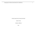
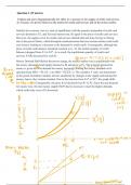
1.3. Introduction 1.4.Basic Structure of Electric Machines
An electric machine continuously converts electrical The structure of electric machine has two major
input to mechanical output or vice versa. components, stator and rotor, separated by the air gap, as
illustrated in Fig. 1.3.
The process of translation is known as electromechanical
energy conversion, which is reversible.
Conversion from mechanical to electrical: a generator.
Conversion from electrical to mechanical: a motor.
Primary quantities in electrical system are voltage and
current, while the analogous quantities in the mechanical
system are torque and speed.
Fig.1.3. Structure of electric machines. (a) Cylindrical machine (uniform air
gap) (b) Salient pole machine (non-uniform air gap).
Stator: This part of the machine does not move and normally is the outer
frame of the machine.
Rotor: This part of the machine is free to move and normally is the inner
Fig.1.1 Electromechanical conversion Fig.1.2. Coupling field between part of the machine
electrical and mechanical systems
3
4
10/22/2023 Electrical Machines I Lecture Notes 10/22/2023 Electrical Machines I Lecture Notes
1. DC MACHINES 1. DC MACHINES
1.5. Classification of electric machines 1.6 DC Machine
According to type of excitation (AC or DC) , one can define the following In the DC machine, the field winding is placed on the stator and
types of machines: the armature winding on the rotor.
• Direct-current machines: DC in both stator and rotor A dc current is passed through the field winding to produce
• Synchronous machines: AC in one winding, DC in the other flux in the machine.
• Induction machines: AC in both Voltage induced in the armature winding is alternating.
A mechanical commutator and a brush assembly function as a
Table 1.1 Configurations of the three types of electric machines
rectifier or inverter, making the armature terminal voltage
unidirectional.
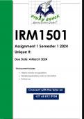
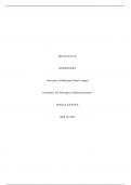
1.6.1. The action of a commutator
Consider a single-loop conductor mounted between permanent
magnets (Figure 1.4).
A voltage is applied at points A and B in Figure 1.4(a).
A force, F, acts on the loop due to the interaction of the magnetic
field of the permanent magnets and the magnetic field created by
the current flowing in the loop.
This force is proportional to the flux density, B, the current
flowing, I, and the effective length of the conductor, l, i.e. F =BIl.
5
6
10/22/2023 Electrical Machines I Lecture Notes 10/22/2023 Electrical Machines I Lecture Notes
1
, 10/22/2023
1. DC MACHINES 1. DC MACHINES
1.6 DC Machine 1.6.1. The action of a commutator Cont’
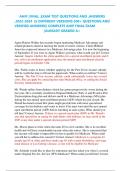
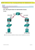
1.6.1. The action of a commutator Cont’ This apparent reversal in the direction of current flow is achieved by a process called
commutation.
In Figure 1.5(a), when a direct voltage is applied at A and B, the forces act to give
continuous rotation in an anticlockwise direction.
The voltage is applied to the rotating segments by stationary brushes, which slide on
the commutator material.
Poor commutation results in sparking at the trailing edge of the brushes.
This can be improved by using interpoles , high resistance brushes, or using brushes
spanning several commutator segments.
Figure 1.4
The force has two parts (all from Fleming’s left-hand rule):
1. one acting vertically downwards due to current flowing from C to D
2. the other acting vertically upwards due to current flowing from E to
F
If the loop is free to rotate, then when it has rotated through 180◦, the
conductors are as shown in Figure 1.4(b).
For rotation to continue in the same direction, it is necessary for the
current flow to be as shown in Figure 1.6(b), i.e. from D to C and from F
to E. Figure 1.5 Figure 1.6
7
8
10/22/2023 Electrical Machines I Lecture Notes 10/22/2023 Electrical Machines I Lecture Notes
1. DC MACHINES 1. DC MACHINES
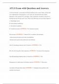
1.6.2 DC Machine Construction 1.6.2 DC Machine Construction
The basic parts of any D.C. machine (Figure 1.7), comprise: (b) a rotating part called the armature mounted in bearings housed
(a) a stationary part called the stator having, in the stator and having,
(i) a steel ring called the yoke, to which are attached (iv) a laminated cylinder of iron or steel called the core, on which teeth
(ii) the magnetic poles, around which are the are cut to house the
(iii) field windings, i.e. many turns of a conductor wound round the pole (v) armature winding, i.e. a single or multi-loop conductor system and
core; current passing through this conductor creates an electromagnet (vi) the commutator.
Armature windings can be divided into two groups:
These are called wave windings and lap windings.
(a) In wave windings there are two paths in parallel
irrespective of the number of poles, each path supplying half the
total current output. Wave wound generators produce high
voltage, low current outputs.
(b) In lap windings there are as many paths in parallel as the
machine has poles. The total current output divides equally
between them. Lap wound generators produce high current,
Figure 1.7 low voltage output.
10
9
10/22/2023 Electrical Machines I Lecture Notes 10/22/2023 Electrical Machines I Lecture Notes
1. DC MACHINES 1. DC MACHINES
1.6.3 Shunt, series and compound windings 1.6.4 E.m.f. generated in an armature winding
Let 𝑍 =number of armature conductors,
Φ=useful flux per pole, in webers
𝑝 =number of pairs of poles and 𝑛 =armature speed in rev/s
The e.m.f. generated by the armature is equal to the e.m.f. generated
by one of the parallel paths.
Each conductor passes 2p poles per revolution and thus cuts
Figure 1.8
2p𝚽 webers of magnetic flux per revolution.
In shunt wound d.c. machine the field winding is connected in parallel with the Hence flux cut by one conductor per second=2pΦn Wb and so the
armature, (Figure 1. 8(a)). average e.m.f. E generated per conductor is given by:
If the field winding is connected in series with the armature, as shown in Figure
1.8 (b), then the machine is said to be series wound.
A compound wound machine has a combination of series and shunt windings. 𝐸 = 2𝑝Φ𝑛 volts (since 1 volt=1Weber per second)
Armature reaction is the effect that the magnetic field produced by the Let c = number of parallel paths through the winding between positive
armature current has on the magnetic field produced by the field system.
and negative brushes
Armature reaction effect is reduced by fitting compensating windings.
In a generator, armature reaction results in a reduced output voltage, and c = 2 for a wave winding
in a motor, armature reaction results in increased speed. c = 2p for a lap winding
12
11
10/22/2023 Electrical Machines I Lecture Notes 10/22/2023 Electrical Machines I Lecture Notes
2
1. DC MACHINES 1. DC MACHINES
1.1.Objectives 1.2. Content
Construction of DC machines: Yoke, Main poles, Field /Magnetizing
By the end of the sub—module unit, the trainee should coils, Armature, Commutator, Brushes and brush gear, bearings
be able:
Principle of operation of DC machines
a) Describe the construction of DC machines Classification of DC machines: Separately excited, self-excited, Long
compound, short compound
b) Explain the principle of operation of DC machines
Face-plate starter: Need, protective devices, operation
c) Describe the classification of DC machines
Armature reaction and commutation
d) Describe the operation of face plate starter Characteristics of DC machines: Generators, Motors,
e) Explain armature reaction and commutation Application of DC machines
f) Describe the characteristics of DC machines
REFERENCES
g) State the applications of DC machines
1.J. O. Bird, “Electrical Circuit Theory and Technology”, Routledge,
REFERNCES: J. O. Bird, “Electrical Circuit Theory and 5th Edition, ISBN: 978-0-415-66286-4, 2014.
Technology”, Routledge, 5th Edition,
2.P.C.Sen, “Principles of Electric Machines and Power Electronics”,
ISBN: 918-0-415-66286-4, 2014. John Wiley and Sons, 2nd Edition, 1997.
Electrical Machines I Lecture Notes Electrical Machines I Lecture Notes
10/22/2023 10/22/2023
1
2
1. DC MACHINES 1. DC MACHINES
1.3. Introduction 1.4.Basic Structure of Electric Machines
An electric machine continuously converts electrical The structure of electric machine has two major
input to mechanical output or vice versa. components, stator and rotor, separated by the air gap, as
illustrated in Fig. 1.3.
The process of translation is known as electromechanical
energy conversion, which is reversible.
Conversion from mechanical to electrical: a generator.
Conversion from electrical to mechanical: a motor.
Primary quantities in electrical system are voltage and
current, while the analogous quantities in the mechanical
system are torque and speed.
Fig.1.3. Structure of electric machines. (a) Cylindrical machine (uniform air
gap) (b) Salient pole machine (non-uniform air gap).
Stator: This part of the machine does not move and normally is the outer
frame of the machine.
Rotor: This part of the machine is free to move and normally is the inner
Fig.1.1 Electromechanical conversion Fig.1.2. Coupling field between part of the machine
electrical and mechanical systems
3
4
10/22/2023 Electrical Machines I Lecture Notes 10/22/2023 Electrical Machines I Lecture Notes
1. DC MACHINES 1. DC MACHINES
1.5. Classification of electric machines 1.6 DC Machine
According to type of excitation (AC or DC) , one can define the following In the DC machine, the field winding is placed on the stator and
types of machines: the armature winding on the rotor.
• Direct-current machines: DC in both stator and rotor A dc current is passed through the field winding to produce
• Synchronous machines: AC in one winding, DC in the other flux in the machine.
• Induction machines: AC in both Voltage induced in the armature winding is alternating.
A mechanical commutator and a brush assembly function as a
Table 1.1 Configurations of the three types of electric machines
rectifier or inverter, making the armature terminal voltage
unidirectional.
1.6.1. The action of a commutator
Consider a single-loop conductor mounted between permanent
magnets (Figure 1.4).
A voltage is applied at points A and B in Figure 1.4(a).
A force, F, acts on the loop due to the interaction of the magnetic
field of the permanent magnets and the magnetic field created by
the current flowing in the loop.
This force is proportional to the flux density, B, the current
flowing, I, and the effective length of the conductor, l, i.e. F =BIl.
5
6
10/22/2023 Electrical Machines I Lecture Notes 10/22/2023 Electrical Machines I Lecture Notes
1
, 10/22/2023
1. DC MACHINES 1. DC MACHINES
1.6 DC Machine 1.6.1. The action of a commutator Cont’
1.6.1. The action of a commutator Cont’ This apparent reversal in the direction of current flow is achieved by a process called
commutation.
In Figure 1.5(a), when a direct voltage is applied at A and B, the forces act to give
continuous rotation in an anticlockwise direction.
The voltage is applied to the rotating segments by stationary brushes, which slide on
the commutator material.
Poor commutation results in sparking at the trailing edge of the brushes.
This can be improved by using interpoles , high resistance brushes, or using brushes
spanning several commutator segments.
Figure 1.4
The force has two parts (all from Fleming’s left-hand rule):
1. one acting vertically downwards due to current flowing from C to D
2. the other acting vertically upwards due to current flowing from E to
F
If the loop is free to rotate, then when it has rotated through 180◦, the
conductors are as shown in Figure 1.4(b).
For rotation to continue in the same direction, it is necessary for the
current flow to be as shown in Figure 1.6(b), i.e. from D to C and from F
to E. Figure 1.5 Figure 1.6
7
8
10/22/2023 Electrical Machines I Lecture Notes 10/22/2023 Electrical Machines I Lecture Notes
1. DC MACHINES 1. DC MACHINES
1.6.2 DC Machine Construction 1.6.2 DC Machine Construction
The basic parts of any D.C. machine (Figure 1.7), comprise: (b) a rotating part called the armature mounted in bearings housed
(a) a stationary part called the stator having, in the stator and having,
(i) a steel ring called the yoke, to which are attached (iv) a laminated cylinder of iron or steel called the core, on which teeth
(ii) the magnetic poles, around which are the are cut to house the
(iii) field windings, i.e. many turns of a conductor wound round the pole (v) armature winding, i.e. a single or multi-loop conductor system and
core; current passing through this conductor creates an electromagnet (vi) the commutator.
Armature windings can be divided into two groups:
These are called wave windings and lap windings.
(a) In wave windings there are two paths in parallel
irrespective of the number of poles, each path supplying half the
total current output. Wave wound generators produce high
voltage, low current outputs.
(b) In lap windings there are as many paths in parallel as the
machine has poles. The total current output divides equally
between them. Lap wound generators produce high current,
Figure 1.7 low voltage output.
10
9
10/22/2023 Electrical Machines I Lecture Notes 10/22/2023 Electrical Machines I Lecture Notes
1. DC MACHINES 1. DC MACHINES
1.6.3 Shunt, series and compound windings 1.6.4 E.m.f. generated in an armature winding
Let 𝑍 =number of armature conductors,
Φ=useful flux per pole, in webers
𝑝 =number of pairs of poles and 𝑛 =armature speed in rev/s
The e.m.f. generated by the armature is equal to the e.m.f. generated
by one of the parallel paths.
Each conductor passes 2p poles per revolution and thus cuts
Figure 1.8
2p𝚽 webers of magnetic flux per revolution.
In shunt wound d.c. machine the field winding is connected in parallel with the Hence flux cut by one conductor per second=2pΦn Wb and so the
armature, (Figure 1. 8(a)). average e.m.f. E generated per conductor is given by:
If the field winding is connected in series with the armature, as shown in Figure
1.8 (b), then the machine is said to be series wound.
A compound wound machine has a combination of series and shunt windings. 𝐸 = 2𝑝Φ𝑛 volts (since 1 volt=1Weber per second)
Armature reaction is the effect that the magnetic field produced by the Let c = number of parallel paths through the winding between positive
armature current has on the magnetic field produced by the field system.
and negative brushes
Armature reaction effect is reduced by fitting compensating windings.
In a generator, armature reaction results in a reduced output voltage, and c = 2 for a wave winding
in a motor, armature reaction results in increased speed. c = 2p for a lap winding
12
11
10/22/2023 Electrical Machines I Lecture Notes 10/22/2023 Electrical Machines I Lecture Notes
2