Unit 2: Electricity
Standard Circuit Symbols
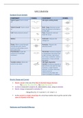
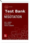
COMPONENT SYMBOL COMPONENT SYMBOL
Switch (open): Turns a circuit LED (light emitting diode)
off
Switch (closed): Turns a circuit Bulb / lamp: Electrical current
on heats the filament in the bulb so
it emits light
Cell: Pushes electrons around Fuse: Designed to melt and
break the circuit
Battery Voltmeter: Measures the
voltage/p.d.
Diode: Allows current through Ammeter: Measures the
one direction only. Used to electrical current
convert an alternating current
into a direct one.
Fixed Resistor: Limits the Thermistor: Resistance depends
current in a circuit (fixed on temperature (low temp it has
resistance) a high resistance, high temp it
has a lower resistance). Used in
thermostats or heat-activated
fire alarms.
Variable resistor: Allows the LDR (light dependent
current to be varied resistor): Resistance depends on
light intensity (low light has high
resistance, as light intensity
increases, resistance decreases.
Used as sensor in
cameras/security lights that
come on instantly as it darkens.
Electric Charge and Current
Electric current is the rate of the flow of electrical charge/electrons
- The greater the rate of flow, the higher the current
Current is measured in amperes (A), abbreviated to amps, using an ammeter.
Electric charge is measured in coulombs (C)
charge flow(Q , C)=current ( I , A)×time (t , s)
As the current in a single, closed loop of a circuit has nowhere else to go the current is the
same at all points in the loop.
Resistance and Potential Difference
, The resistance of a component is the measure of how it resists the flow of charge.
The higher the resistance:
- The more difficult it is for charge to flow
- The lower the current
Resistance is measured in ohms (Ω)
Factors affecting resistance:
- Diameter of wire
Thinner wire = more resistance
- Temperature of wire
Hotter wire = more resistance
- Length of wire
Longer wire = more resistance
- Material of wire
Lower the conductivity = more resistance
Potential difference tells us the difference in electrical potential from one point in a circuit
to another.
- It can be thought of as electrical push
The bigger the potential difference across a component:
- The greater the flow of charge through the component
- The bigger the current
Potential difference is measured in volts (V) using a voltmeter
Potential difference, current and resistance are linked by the equation:
potential difference (V )=current (I , A )× resistance(R , Ω)
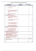
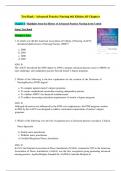
Required Practical: Investigate the factors that affect the resistance of an electrical component.
Method: how length affects the resistance of a Control variables: current (if it was too high it
wire would cause the wire to get hot and change its
Set up the standard test circuit. resistance)
Pre-test the circuit and adjust the supply voltage to Independent variable: length of the wire
ensure that there is a measurable difference in Dependent variable: voltage
readings taken at the shortest and longest lengths. Hazards/Risks: - current flowing through the wire
Record the voltage and current at a range of can cause it to get very hot.- to avoid being burned
lengths, using crocodile clips to grip the wire at by the wire: + a low supply voltage should be used+
different points. adjust the variable resistor to keep the current low
Use the variable resistor to keep the current
through the wire the same at each length.
Use the voltage and current measurements to
calculate the resistance.
Considerations, Mistakes and Errors- Adjusting the supply voltage to ensure as wide a range of results as
possible is important, as measurements could be limited by the precision of the measuring equipment.-
The range of measurements to be tested should always include at least five measurements at reasonable
intervals. This allows for patterns to be seen without missing what happens in between, but also without
Resistors,
taking large Bulbs
numbers and Diodes measurements.
of unnecessary
Standard Circuit Symbols
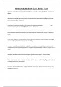
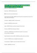
COMPONENT SYMBOL COMPONENT SYMBOL
Switch (open): Turns a circuit LED (light emitting diode)
off
Switch (closed): Turns a circuit Bulb / lamp: Electrical current
on heats the filament in the bulb so
it emits light
Cell: Pushes electrons around Fuse: Designed to melt and
break the circuit
Battery Voltmeter: Measures the
voltage/p.d.
Diode: Allows current through Ammeter: Measures the
one direction only. Used to electrical current
convert an alternating current
into a direct one.
Fixed Resistor: Limits the Thermistor: Resistance depends
current in a circuit (fixed on temperature (low temp it has
resistance) a high resistance, high temp it
has a lower resistance). Used in
thermostats or heat-activated
fire alarms.
Variable resistor: Allows the LDR (light dependent
current to be varied resistor): Resistance depends on
light intensity (low light has high
resistance, as light intensity
increases, resistance decreases.
Used as sensor in
cameras/security lights that
come on instantly as it darkens.
Electric Charge and Current
Electric current is the rate of the flow of electrical charge/electrons
- The greater the rate of flow, the higher the current
Current is measured in amperes (A), abbreviated to amps, using an ammeter.
Electric charge is measured in coulombs (C)
charge flow(Q , C)=current ( I , A)×time (t , s)
As the current in a single, closed loop of a circuit has nowhere else to go the current is the
same at all points in the loop.
Resistance and Potential Difference
, The resistance of a component is the measure of how it resists the flow of charge.
The higher the resistance:
- The more difficult it is for charge to flow
- The lower the current
Resistance is measured in ohms (Ω)
Factors affecting resistance:
- Diameter of wire
Thinner wire = more resistance
- Temperature of wire
Hotter wire = more resistance
- Length of wire
Longer wire = more resistance
- Material of wire
Lower the conductivity = more resistance
Potential difference tells us the difference in electrical potential from one point in a circuit
to another.
- It can be thought of as electrical push
The bigger the potential difference across a component:
- The greater the flow of charge through the component
- The bigger the current
Potential difference is measured in volts (V) using a voltmeter
Potential difference, current and resistance are linked by the equation:
potential difference (V )=current (I , A )× resistance(R , Ω)
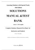
Required Practical: Investigate the factors that affect the resistance of an electrical component.
Method: how length affects the resistance of a Control variables: current (if it was too high it
wire would cause the wire to get hot and change its
Set up the standard test circuit. resistance)
Pre-test the circuit and adjust the supply voltage to Independent variable: length of the wire
ensure that there is a measurable difference in Dependent variable: voltage
readings taken at the shortest and longest lengths. Hazards/Risks: - current flowing through the wire
Record the voltage and current at a range of can cause it to get very hot.- to avoid being burned
lengths, using crocodile clips to grip the wire at by the wire: + a low supply voltage should be used+
different points. adjust the variable resistor to keep the current low
Use the variable resistor to keep the current
through the wire the same at each length.
Use the voltage and current measurements to
calculate the resistance.
Considerations, Mistakes and Errors- Adjusting the supply voltage to ensure as wide a range of results as
possible is important, as measurements could be limited by the precision of the measuring equipment.-
The range of measurements to be tested should always include at least five measurements at reasonable
intervals. This allows for patterns to be seen without missing what happens in between, but also without
Resistors,
taking large Bulbs
numbers and Diodes measurements.
of unnecessary