EXP. 07:
THE LAWS OF ELECTRICAL CIRCUITS
LAB REPORT TEMPLATE
TOTAL MARKS: 25
_______________________________________________________________________________________
SURNAME: NGOBESE STUDENT #: 2739414
FIRST NAME: NONTANDO DATE: 16/10/2023
TITLE: THE LAWS OF ELECTRICAL CIRCUITS
INTRODUCTION [1 mark]
AIM:
To investigate the laws governing current and potential difference in electrical circuits.
RESULTS & CALCULATIONS
For each of the 4 tables:
(i) Each Table MUST include the error estimate, based on the relevant instrument shown in the
accompanying figures.
(ii) Express the relationship between the currents or the potential differences in the form of an
equation;
AND
(iii)Discuss the results in relation to the equation being examined.
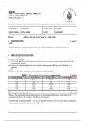
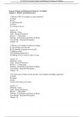
Table 1. Measurement of the current in a series circuit. [2 marks]
R2 (Ω) ±0.5 Ω I1 (A) ± 0.5A I2 (A) ± 0.5 A I3 (A) ±0.5A
1.0 0.75 0.75 0.75
2.0 0.7 0.7 0.7
3.0 0.55 0.55 0.55
4.0 0.5 0.5 0.5
5.0 0.45 0.45 0.45
Data Analysis and Discussion [1 mark]
Express the relationship between the currents or the potential differences in the form of an
equation and discuss the results in relation to the equation.
From the data recorded in Table 1, we can see that the currents are of the same values or identical
when connected in series, therefore (I1 = I2 = I3).
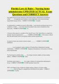
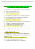
, Table 2. Measurement of the potential in a series circuit. [1 mark]
R2 (Ω) ± 0.5 Ω V1 (V) ± 0.1V V2 (V) ±0.1V V3 (V) ±0.1V
1.0 5.4 4.4 1.0
2.0 5.4 3.8 1.6
3.0 5.4 3.3 2.1
4.0 5.4 2.9 2.5
5.0 5.4 2.6 2.8
Data Analysis and Discussion [1 mark]
Express the relationship between the currents or the potential differences in the form of an
equation and discuss the results in relation to the equation.
From the table above, we can see that the voltage V1 is equal to the sum of the voltages V2 and
V3. There is a summation of voltages in a series connection, such that V1 = V2 + V3.
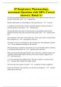
Table 3. Measurement of the potential in a parallel circuit. [1 mark]
R2 (Ω) ±0.5 Ω V1 (V) ±0.1V V2 (V) ±0.1V V3 (V) ± 0.1V
5.0 5.4 5,4 5.4
10.0 5.4 5.4 5.4
15.0 5.4 5.4 5.4
20.0 5.4 5.4 5.4
25.0 5.4 5.4 5.4
Data Analysis and Discussion [1 mark]
Express the relationship between the currents or the potential differences in the form of an
equation and discuss the results in relation to the equation.
From the table above, we can see that the different voltages V1, V2 and V3 are equal to one another in a
parallel connection …therefore V1 = V2 + V3.
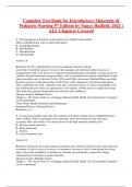
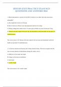
Table 4. Measurement of the current in a parallel circuit. [1 mark]
R2 (Ω) ± …… I1 (A) ±0.5A I2 (A) ± 0.5A I3 (A) ±0.5A
5.0 1.10 0.15 0.90
10.0 0.70 0.15 0.45
15.0 0.50 0.15 0.30
20.0 0.40 0.15 0.20
25.0 0.35 0.15 0.15
THE LAWS OF ELECTRICAL CIRCUITS
LAB REPORT TEMPLATE
TOTAL MARKS: 25
_______________________________________________________________________________________
SURNAME: NGOBESE STUDENT #: 2739414
FIRST NAME: NONTANDO DATE: 16/10/2023
TITLE: THE LAWS OF ELECTRICAL CIRCUITS
INTRODUCTION [1 mark]
AIM:
To investigate the laws governing current and potential difference in electrical circuits.
RESULTS & CALCULATIONS
For each of the 4 tables:
(i) Each Table MUST include the error estimate, based on the relevant instrument shown in the
accompanying figures.
(ii) Express the relationship between the currents or the potential differences in the form of an
equation;
AND
(iii)Discuss the results in relation to the equation being examined.
Table 1. Measurement of the current in a series circuit. [2 marks]
R2 (Ω) ±0.5 Ω I1 (A) ± 0.5A I2 (A) ± 0.5 A I3 (A) ±0.5A
1.0 0.75 0.75 0.75
2.0 0.7 0.7 0.7
3.0 0.55 0.55 0.55
4.0 0.5 0.5 0.5
5.0 0.45 0.45 0.45
Data Analysis and Discussion [1 mark]
Express the relationship between the currents or the potential differences in the form of an
equation and discuss the results in relation to the equation.
From the data recorded in Table 1, we can see that the currents are of the same values or identical
when connected in series, therefore (I1 = I2 = I3).
, Table 2. Measurement of the potential in a series circuit. [1 mark]
R2 (Ω) ± 0.5 Ω V1 (V) ± 0.1V V2 (V) ±0.1V V3 (V) ±0.1V
1.0 5.4 4.4 1.0
2.0 5.4 3.8 1.6
3.0 5.4 3.3 2.1
4.0 5.4 2.9 2.5
5.0 5.4 2.6 2.8
Data Analysis and Discussion [1 mark]
Express the relationship between the currents or the potential differences in the form of an
equation and discuss the results in relation to the equation.
From the table above, we can see that the voltage V1 is equal to the sum of the voltages V2 and
V3. There is a summation of voltages in a series connection, such that V1 = V2 + V3.
Table 3. Measurement of the potential in a parallel circuit. [1 mark]
R2 (Ω) ±0.5 Ω V1 (V) ±0.1V V2 (V) ±0.1V V3 (V) ± 0.1V
5.0 5.4 5,4 5.4
10.0 5.4 5.4 5.4
15.0 5.4 5.4 5.4
20.0 5.4 5.4 5.4
25.0 5.4 5.4 5.4
Data Analysis and Discussion [1 mark]
Express the relationship between the currents or the potential differences in the form of an
equation and discuss the results in relation to the equation.
From the table above, we can see that the different voltages V1, V2 and V3 are equal to one another in a
parallel connection …therefore V1 = V2 + V3.
Table 4. Measurement of the current in a parallel circuit. [1 mark]
R2 (Ω) ± …… I1 (A) ±0.5A I2 (A) ± 0.5A I3 (A) ±0.5A
5.0 1.10 0.15 0.90
10.0 0.70 0.15 0.45
15.0 0.50 0.15 0.30
20.0 0.40 0.15 0.20
25.0 0.35 0.15 0.15