Solution Manual For
Digital Fundamentals, Global Edition, 11th edition Thomas L Floyd
Chapter 1-15
PART 1
Problem Solutions
CHAPTER 1
INTRODUCTORY CONCEPTS
Section 1-1 Digital and Analog Quantities
1. Digital data can be transmitted and stored more efficiently and reliably than analog data. Also,
digital circuits are simpler to implement and there is a greater immunity to noisy environments.
2. Analog quantities.
3. Thermometer – measures temperature
Sphygmomanometer – measures blood pressure
Photometer – measures light
Section 1-2 Binary Digits, Logic Levels, and Digital Waveforms
4. No. Because a digital system involves only two states, 1 or zero, represented by two voltage levels,
high or low
1
,Chapter 2
Note: As there are only two states which can be depicted with respect to the voltage ( low or high
and low means 0, high means 1 ), A digital system can take only two values.
5. HIGH is 1 and LOW is 0
(a) 11000011
(b) 10101010
6. 1 is HIGH and 0 is LOW
(a) HIGH, LOW, LOW, LOW, LOW, ONE, ZERO, ONE
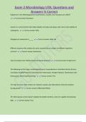
(b) HIGH, HIGH, HIGH, HIGH, LOW, LOW, HIGH, HIGH7. See Figure 1-2.
Ampl
= 10 V
tPW = 2.7 s
8. Yes. Because given waveform is composed of a series of pulses.
1 1
9. f= = 0.25 kHz = 250 Hz
T 4 ms
10. The waveform in Figure 1-61 is periodic because it repeats at a fixed interval.
11. tW = 2 ms; T = 4 ms
t 2 ms
% duty cycle = W 100 100 = 50%
T 4 ms
12. Each bit time = 2ms
Serial transfer time = (8 bits)(2ms/bit) = 16ms
13. Each bit time = 1 s
Serial transfer time = (8 bits)(1 s/bit) = 8 s
Parallel transfer time = 1 bit time = 1 s
2
, Chapter 2
14. T = 1/f = 1/(4KHz) = 0.25ms
Section 1-3 Basic Logic Functions
15. LON = SW1 + SW2 + SW1 SW2
16. NOT gate
17. OR gate
18. AND gate.
Section 1-4 Combinational and Sequential Logic Functions
19. (a) Subtractor
(b) Multiplier
(c) Multiplexer
(d) Comparator
20. T = 1/20kHz = 0.5μs
Pulse counted = 40ms/0.5μs = 8000
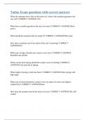
21. See Figure 1-7.
Section 1-5 Introduction to Programmable Logic
22. Synthesis: This refers to the translation of design into a netlist which has a standard form and is
device independent
Implementation: This refers to the mapping of the logic structures described by the netlist, into the
actual structure of the specific device being programmed
Compiler: A compiler is a program that controls the design flow process and translates the source
code into object code in a format that can be logically tested or downloaded to a target device
23. (a) SPLD: Simple Programmable Logic Device
3
, Chapter 2
(b) CPLD: Complex Programmable Logic Device
(c) HDL: Hardware Description Language
(d) FPGA: Field-Programmable Gate Array
(e) GAL: Generic Array Logic
24. (a) Design entry: The step in a programmable logic design flow where a description of the
circuit is entered in either schematic (graphic) form or in text form using an HDL.
(b) Simulation: The step in a design flow where the entered design is simulated based on
defined input waveforms.
(c) Compilation: A program process that controls the design flow process and translates a
design source code to object code for testing and downloading.
(d) Download: The process in which the design is transferred from software to hardware.
25. Place-and-route or fitting is the process where the logic structures described by the netlist are
mapped into the actual structure of the specific target device. This results in an output called a
bitstream.
Section 1-6 Fixed-Function Logic Devices
26. Based on the technique in which they are mounted on a printed circuit board, the Integrated circuit
packages are classified as hole-mounted or surface-mounted packages.
27. Circuits with complexities of from 100 to 10,000 equivalent gates are classified as large scale
integration (LSI).
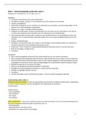
28. See Figure 1-8.
Section 1-7 Test and Measurement Instruments
29. 8V
4
Digital Fundamentals, Global Edition, 11th edition Thomas L Floyd
Chapter 1-15
PART 1
Problem Solutions
CHAPTER 1
INTRODUCTORY CONCEPTS
Section 1-1 Digital and Analog Quantities
1. Digital data can be transmitted and stored more efficiently and reliably than analog data. Also,
digital circuits are simpler to implement and there is a greater immunity to noisy environments.
2. Analog quantities.
3. Thermometer – measures temperature
Sphygmomanometer – measures blood pressure
Photometer – measures light
Section 1-2 Binary Digits, Logic Levels, and Digital Waveforms
4. No. Because a digital system involves only two states, 1 or zero, represented by two voltage levels,
high or low
1
,Chapter 2
Note: As there are only two states which can be depicted with respect to the voltage ( low or high
and low means 0, high means 1 ), A digital system can take only two values.
5. HIGH is 1 and LOW is 0
(a) 11000011
(b) 10101010
6. 1 is HIGH and 0 is LOW
(a) HIGH, LOW, LOW, LOW, LOW, ONE, ZERO, ONE
(b) HIGH, HIGH, HIGH, HIGH, LOW, LOW, HIGH, HIGH7. See Figure 1-2.
Ampl
= 10 V
tPW = 2.7 s
8. Yes. Because given waveform is composed of a series of pulses.
1 1
9. f= = 0.25 kHz = 250 Hz
T 4 ms
10. The waveform in Figure 1-61 is periodic because it repeats at a fixed interval.
11. tW = 2 ms; T = 4 ms
t 2 ms
% duty cycle = W 100 100 = 50%
T 4 ms
12. Each bit time = 2ms
Serial transfer time = (8 bits)(2ms/bit) = 16ms
13. Each bit time = 1 s
Serial transfer time = (8 bits)(1 s/bit) = 8 s
Parallel transfer time = 1 bit time = 1 s
2
, Chapter 2
14. T = 1/f = 1/(4KHz) = 0.25ms
Section 1-3 Basic Logic Functions
15. LON = SW1 + SW2 + SW1 SW2
16. NOT gate
17. OR gate
18. AND gate.
Section 1-4 Combinational and Sequential Logic Functions
19. (a) Subtractor
(b) Multiplier
(c) Multiplexer
(d) Comparator
20. T = 1/20kHz = 0.5μs
Pulse counted = 40ms/0.5μs = 8000
21. See Figure 1-7.
Section 1-5 Introduction to Programmable Logic
22. Synthesis: This refers to the translation of design into a netlist which has a standard form and is
device independent
Implementation: This refers to the mapping of the logic structures described by the netlist, into the
actual structure of the specific device being programmed
Compiler: A compiler is a program that controls the design flow process and translates the source
code into object code in a format that can be logically tested or downloaded to a target device
23. (a) SPLD: Simple Programmable Logic Device
3
, Chapter 2
(b) CPLD: Complex Programmable Logic Device
(c) HDL: Hardware Description Language
(d) FPGA: Field-Programmable Gate Array
(e) GAL: Generic Array Logic
24. (a) Design entry: The step in a programmable logic design flow where a description of the
circuit is entered in either schematic (graphic) form or in text form using an HDL.
(b) Simulation: The step in a design flow where the entered design is simulated based on
defined input waveforms.
(c) Compilation: A program process that controls the design flow process and translates a
design source code to object code for testing and downloading.
(d) Download: The process in which the design is transferred from software to hardware.
25. Place-and-route or fitting is the process where the logic structures described by the netlist are
mapped into the actual structure of the specific target device. This results in an output called a
bitstream.
Section 1-6 Fixed-Function Logic Devices
26. Based on the technique in which they are mounted on a printed circuit board, the Integrated circuit
packages are classified as hole-mounted or surface-mounted packages.
27. Circuits with complexities of from 100 to 10,000 equivalent gates are classified as large scale
integration (LSI).
28. See Figure 1-8.
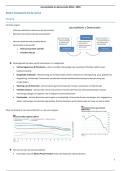
Section 1-7 Test and Measurement Instruments
29. 8V
4