ES2C6 – Power Electronics 3 – Three-Phase Systems
Three-Phase Systems
The UK mains is single-phase, although the pylons which make up the National Grid are carrying
three-phase AC electricity. The Grid distributes one of the three phases to each home and the load
put on each phase is designed to be roughly the same.
Electricity in the UK is generated, transmitted and distributed as three-phase AC. It is most
commonly transferred through a generator; however, it is more increasingly also converted to
electrical energy through other sources such as solar cells.
The National Grid uses ‘four wire’ systems, where there are three live phases and one neutral return.
Generator
Moving a magnet passed a set of coil induces an emf, which then causes a current to flow. The faster
the magnet is moved, the more emf is induced, due to the equation:
𝑑𝜙
𝑉=𝑁 (5)
𝑑𝑡
where 𝜙 is the magnetic flux and 𝑁 is the number of turns in the coil.
The rotor passes three conductors with each rotation and induces an emf in each of them, causing
the three phases. There could be any number of phases, the fact there are three is arbitrary.
Star Connected System
A generator can be connected in a star, or wye, system.
The magnitude of the voltages and currents in each phase is equal:
|𝑉𝑝ℎ𝐴 | = |𝑉𝑝ℎ𝐵 | = |𝑉𝑝ℎ𝐶 |
|𝐼𝑝ℎ𝐴 | = |𝐼𝑝ℎ𝐵 | = |𝐼𝑝ℎ𝐶 |
The impedance of each line is also considered to be equal:
𝑍𝐴 = 𝑍𝐵 = 𝑍𝐶
9
, ES2C6 – Power Electronics 3 – Three-Phase Systems
The current of each phase is equal to the current in each line:
𝐼𝑝ℎ𝐴 = 𝐼𝐴
𝐼𝑝ℎ𝐵 = 𝐼𝐵
𝐼𝑝ℎ𝐶 = 𝐼𝐶
The only difference between the phases is the phase angle, of which each phase is 120° different
from the others, as there are 360° to be split between the three phases.
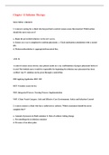
If the voltages are in the order of phase A, phase B then phase C, it is a positive sequence system.
This means that, assuming phase A is at 0°, phase B will be at −120° and phase C at −240°. The
three voltages can be drawn as a vector diagram, rotating counter-clockwise in a positive system:
𝑉𝐴 = 𝑉𝑚 cos(𝜔𝑡 + 𝜙)
𝑉𝐵 = 𝑉𝑚 cos(𝜔𝑡 + 𝜙 − 120)
𝑉𝐶 = 𝑉𝑚 cos(𝜔𝑡 + 𝜙 − 240)
In a negative sequence system phase A leads phase C by 120°, which in turn leads phase B by 120°,
so the order is ACB:
𝑉𝐴 = 𝑉𝑚 cos(𝜔𝑡 + 𝜙)
𝑉𝐵 = 𝑉𝑚 cos(𝜔𝑡 + 𝜙 − 240)
𝑉𝐶 = 𝑉𝑚 cos(𝜔𝑡 + 𝜙 − 120)
The rotation direction of the rotor within the stator determines the sequence of the phases. To
connect a generator to the grid the voltage, frequency and phase sequence must be synchronised. In
10
Three-Phase Systems
The UK mains is single-phase, although the pylons which make up the National Grid are carrying
three-phase AC electricity. The Grid distributes one of the three phases to each home and the load
put on each phase is designed to be roughly the same.
Electricity in the UK is generated, transmitted and distributed as three-phase AC. It is most
commonly transferred through a generator; however, it is more increasingly also converted to
electrical energy through other sources such as solar cells.
The National Grid uses ‘four wire’ systems, where there are three live phases and one neutral return.
Generator
Moving a magnet passed a set of coil induces an emf, which then causes a current to flow. The faster
the magnet is moved, the more emf is induced, due to the equation:
𝑑𝜙
𝑉=𝑁 (5)
𝑑𝑡
where 𝜙 is the magnetic flux and 𝑁 is the number of turns in the coil.
The rotor passes three conductors with each rotation and induces an emf in each of them, causing
the three phases. There could be any number of phases, the fact there are three is arbitrary.
Star Connected System
A generator can be connected in a star, or wye, system.
The magnitude of the voltages and currents in each phase is equal:
|𝑉𝑝ℎ𝐴 | = |𝑉𝑝ℎ𝐵 | = |𝑉𝑝ℎ𝐶 |
|𝐼𝑝ℎ𝐴 | = |𝐼𝑝ℎ𝐵 | = |𝐼𝑝ℎ𝐶 |
The impedance of each line is also considered to be equal:
𝑍𝐴 = 𝑍𝐵 = 𝑍𝐶
9
, ES2C6 – Power Electronics 3 – Three-Phase Systems
The current of each phase is equal to the current in each line:
𝐼𝑝ℎ𝐴 = 𝐼𝐴
𝐼𝑝ℎ𝐵 = 𝐼𝐵
𝐼𝑝ℎ𝐶 = 𝐼𝐶
The only difference between the phases is the phase angle, of which each phase is 120° different
from the others, as there are 360° to be split between the three phases.
If the voltages are in the order of phase A, phase B then phase C, it is a positive sequence system.
This means that, assuming phase A is at 0°, phase B will be at −120° and phase C at −240°. The
three voltages can be drawn as a vector diagram, rotating counter-clockwise in a positive system:
𝑉𝐴 = 𝑉𝑚 cos(𝜔𝑡 + 𝜙)
𝑉𝐵 = 𝑉𝑚 cos(𝜔𝑡 + 𝜙 − 120)
𝑉𝐶 = 𝑉𝑚 cos(𝜔𝑡 + 𝜙 − 240)
In a negative sequence system phase A leads phase C by 120°, which in turn leads phase B by 120°,
so the order is ACB:
𝑉𝐴 = 𝑉𝑚 cos(𝜔𝑡 + 𝜙)
𝑉𝐵 = 𝑉𝑚 cos(𝜔𝑡 + 𝜙 − 240)
𝑉𝐶 = 𝑉𝑚 cos(𝜔𝑡 + 𝜙 − 120)
The rotation direction of the rotor within the stator determines the sequence of the phases. To
connect a generator to the grid the voltage, frequency and phase sequence must be synchronised. In
10