Unit 34 Circuit Simulation & Analysis Using SPICE Assignment 2
For this assignment, I
will firstly begin by
describing how
computer aided design
(CAD) software is used
to analyse an electronic
circuit prior to
manufacture.
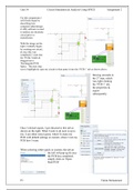
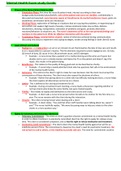
With the image on the
right, I initially began
by creating my circuit,
& once this was
completed, I went into
the ‘PCBs’ folder &
dragged out a
‘Rectangular PCB
Space.’ The next step
was to highlight & copy my circuit to then paste it into the ‘PCB 1’ tab as shown above.
Moving onwards to
the 2nd step, which
was right clicking
the ‘PCB 1’ tab,
the properties &
export
subsequently.
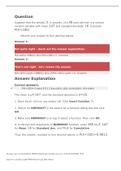
Once I clicked export, I got directed to this tab as
shown on the right. What I want to do next is up to
me; I can either select quick, which’ll create my
PCB with default settings or custom, where I can my
PCB how I want.
When selecting either quick or custom, the tab on
the left will pop up & once
the PCB has completed,
simply click on ‘Open
Real-PCB’
P3 Fahim Mohammed
For this assignment, I
will firstly begin by
describing how
computer aided design
(CAD) software is used
to analyse an electronic
circuit prior to
manufacture.
With the image on the
right, I initially began
by creating my circuit,
& once this was
completed, I went into
the ‘PCBs’ folder &
dragged out a
‘Rectangular PCB
Space.’ The next step
was to highlight & copy my circuit to then paste it into the ‘PCB 1’ tab as shown above.
Moving onwards to
the 2nd step, which
was right clicking
the ‘PCB 1’ tab,
the properties &
export
subsequently.
Once I clicked export, I got directed to this tab as
shown on the right. What I want to do next is up to
me; I can either select quick, which’ll create my
PCB with default settings or custom, where I can my
PCB how I want.
When selecting either quick or custom, the tab on
the left will pop up & once
the PCB has completed,
simply click on ‘Open
Real-PCB’
P3 Fahim Mohammed