NUMBER SYSTEM Binary-Coded Decimal (BCD) – each decimal digit is
represented by a binary code of four-bits (0 – 9 outputs)
Digit → “Digitus” (Finger) 5 6 2
One of the elements that combine to form numbers in a ↓ ↓ ↓
system 0101 0110 0010
In general, in any base n, the number n – 1 will be the
greatest digit and will require regrouping when 1 is added to Straight binary code takes the complete decimal number and
it. represents it in binary.
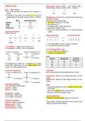
Radix Number/Characters Gray Code (binary reflected code)
Decimal 10 0-9 Frank Gray of Bell Labs in mid 1950s
Binary 2 0,1 Hamming value of 1
Octal 8 0-7 unweighted code; minimum change code
Hexadecimal 16 0-9, A-F only one-bit changes at a time
Primary use: coded representation of a shaft's mechanical
Any base (r) to Decimal position
101001 to base 10
1 0 1 0 . 0 1 Binary to Gray Code Gray Code to Binary
1 x 23 0 x 22 1 x 21 0 x 20 0 x 2-1 1 x 2-2
8 0 2 0 . 0 0.25
= 10.25
When adding BCD numbers, it should not exceed 9
If so, add 0110 (6) to the sum of BCD
1’s complement – change 1’s to 0’s and 0’s to 1’s
2’s complement – adding 1 to the 1’s complement
Carry-Lookahead Adder (CLA)
a type of adder used in digital logic
Find the 1’s complement Find the 2’s complement of 110
reduces the propagation delay
Binary 1’s complement 001 1’s complement
101 010 + 1 Add 1
ASCII
1101 0010 010 2’s complement Decimal Hexadecimal Character
11100 00011
32 20 Blank/space
48 30 0
The simplest way to obtain the 1’s complement of a binary
number with a digital circuit is to use parallel inverters (NOT 65 41 A
circuits). An inverter negates the input. 97 61 a
9’s and 10’s Complement Logic Gates
Find the 9’s complement of 28 Find the 10’s complement of 52 basic building blocks for forming digital electronic circuitry
99 99
- 28 - 52 Positive logic - Binary 0 for low voltage and binary 1 for high
71 9’s complement 47 9’s complement
voltage
Negative logic - Binary 0 for high voltage and binary 1 for low
+ 1
voltage
48 10’s complement
Signed Binary Numbers
Buffer
- carry identification as their polarity
- a special solid-state device used to increase the drive current
Sign bit 0 – positive
at the output.
Sign bit 1 – negative
- also used for isolation between output and input
Hexadecimal – 16 digits - provide an output that is equal to its input
One hex digit = nibble (4 bits)
Two hex digits = byte (8 bits) PULSED OPERATION
voltages that change frequently between two logic levels
Floating Point Numbers
Precision - degree of correctness Timing diagram illustrates graphically how the output levels
Single-precision – 32 bits change in response to input change
Double-precision – 64 bits
Extended-precision – 80 bits
represented by a binary code of four-bits (0 – 9 outputs)
Digit → “Digitus” (Finger) 5 6 2
One of the elements that combine to form numbers in a ↓ ↓ ↓
system 0101 0110 0010
In general, in any base n, the number n – 1 will be the
greatest digit and will require regrouping when 1 is added to Straight binary code takes the complete decimal number and
it. represents it in binary.
Radix Number/Characters Gray Code (binary reflected code)
Decimal 10 0-9 Frank Gray of Bell Labs in mid 1950s
Binary 2 0,1 Hamming value of 1
Octal 8 0-7 unweighted code; minimum change code
Hexadecimal 16 0-9, A-F only one-bit changes at a time
Primary use: coded representation of a shaft's mechanical
Any base (r) to Decimal position
101001 to base 10
1 0 1 0 . 0 1 Binary to Gray Code Gray Code to Binary
1 x 23 0 x 22 1 x 21 0 x 20 0 x 2-1 1 x 2-2
8 0 2 0 . 0 0.25
= 10.25
When adding BCD numbers, it should not exceed 9
If so, add 0110 (6) to the sum of BCD
1’s complement – change 1’s to 0’s and 0’s to 1’s
2’s complement – adding 1 to the 1’s complement
Carry-Lookahead Adder (CLA)
a type of adder used in digital logic
Find the 1’s complement Find the 2’s complement of 110
reduces the propagation delay
Binary 1’s complement 001 1’s complement
101 010 + 1 Add 1
ASCII
1101 0010 010 2’s complement Decimal Hexadecimal Character
11100 00011
32 20 Blank/space
48 30 0
The simplest way to obtain the 1’s complement of a binary
number with a digital circuit is to use parallel inverters (NOT 65 41 A
circuits). An inverter negates the input. 97 61 a
9’s and 10’s Complement Logic Gates
Find the 9’s complement of 28 Find the 10’s complement of 52 basic building blocks for forming digital electronic circuitry
99 99
- 28 - 52 Positive logic - Binary 0 for low voltage and binary 1 for high
71 9’s complement 47 9’s complement
voltage
Negative logic - Binary 0 for high voltage and binary 1 for low
+ 1
voltage
48 10’s complement
Signed Binary Numbers
Buffer
- carry identification as their polarity
- a special solid-state device used to increase the drive current
Sign bit 0 – positive
at the output.
Sign bit 1 – negative
- also used for isolation between output and input
Hexadecimal – 16 digits - provide an output that is equal to its input
One hex digit = nibble (4 bits)
Two hex digits = byte (8 bits) PULSED OPERATION
voltages that change frequently between two logic levels
Floating Point Numbers
Precision - degree of correctness Timing diagram illustrates graphically how the output levels
Single-precision – 32 bits change in response to input change
Double-precision – 64 bits
Extended-precision – 80 bits

