ES191
Contents
Week 1: Fundamentals ..................................................................................................................................................... 3
Charge, Electric Fields and Current ............................................................................................................................... 3
Fundamentals of Charge: Bohr’s Atomic Model ....................................................................................................... 3
Capacitors.................................................................................................................................................................. 4
Permittivity ................................................................................................................................................................ 5
Week 2: ............................................................................................................................................................................. 7
Magnetic Fields ........................................................................................................................................................... 10
Magnetic Field Fundamentals and Flux .................................................................................................................. 10
Magnetic Properties of Materials: .......................................................................................................................... 10
Magnetic Circuits .................................................................................................................................................... 12
Magnetic Field and Electromagnetics ......................................................................................................................... 13
Inductors ................................................................................................................................................................. 13
Transformers ........................................................................................................................................................... 15
Optics and Waves ........................................................................................................................................................ 17
Week 3: Symbols and Conventions in Electric Circuits ................................................................................................... 23
Voltage and Current .................................................................................................................................................... 23
Power and Energy ....................................................................................................................................................... 23
Mechanical Analogy of Ohm’s Law ............................................................................................................................. 23
Basic Active Circuit Elements ...................................................................................................................................... 24
Basic Convention ......................................................................................................................................................... 25
Week 3: Nodal Analysis for DC Circuits ........................................................................................................................... 26
Kirchhoff’s Current Law ............................................................................................................................................... 26
Nodal Analysis ............................................................................................................................................................. 26
Admittance Matrix ...................................................................................................................................................... 27
Mesh Analysis in DC Circuits ........................................................................................................................................... 27
Kirchhoff’s Voltage Law ............................................................................................................................................... 27
Mesh Analysis.............................................................................................................................................................. 28
Impedance Matrix ....................................................................................................................................................... 28
Week 4: Thevenin and Norton Circuits ........................................................................................................................... 29
Thevenin Equivalent Circuits ....................................................................................................................................... 29
Steps for calculating Thevenin Equivalent Circuits.................................................................................................. 29
Norton Equivalent Circuits .......................................................................................................................................... 30
Maximum Power Transfer ........................................................................................................................................... 30
1
,Week 5: RC Circuits ......................................................................................................................................................... 31
Definition of Capacitance ............................................................................................................................................ 31
Capacitor Charging Transient .................................................................................................................................. 31
Week 6: First Order RL Circuits and an Introduction to AC Circuits ................................................................................ 33
Current and Magnetism .............................................................................................................................................. 33
Definition of Inductance ............................................................................................................................................. 33
Mechanical Analogy of Inductance ............................................................................................................................. 34
Inductor Discharge ...................................................................................................................................................... 36
Step Response of an Inductor ..................................................................................................................................... 36
Week 6 (2): Alternating Current (AC) Circuits ................................................................................................................. 36
AC Voltages and Currents ............................................................................................................................................ 36
Reactance in AC Circuits .............................................................................................................................................. 37
Phasor Diagrams ..................................................................................................................................................... 38
Week 6: Alternating Circuits (AC) Circuits (2).................................................................................................................. 39
Complex Impedances .................................................................................................................................................. 39
2
,Week 1: Fundamentals
Charge, Electric Fields and Current
Charge is a fundamental property of matter – it can not be created or destroyed. Electrons have negative charge;
protons have an equal and opposite charge. Charged particles create a field around them, which has the capacity to
attract opposite charged particles and repel like-charged particles. Therefore, this field has energy (potential energy),
energy is defined as having the capacity to do work. This field is called an electric field, E measured in Volts/Metre.
• Charge (Q) – Measured in Coulomb, C
• Charge on an Electron = -1.6 x 10⁻¹⁹C
• Movement of charge, e.g. through a wire, gives an electric current, I
𝑄
• Current: Flow of charge per second 𝐼= 𝑡
• 1A is 1 coulomb or charge transferred in 1 second
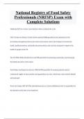
Fundamentals of Charge: Bohr’s Atomic Model
• Niels Bohr proposed an atomic model that suggested that electrons orbit the nucleus, much like the Earth
revolving around the Sun.
• These orbitals (the path by which the electrons orbit the nucleus) have fixed distances and fixed energies.
• The orbitals closest to the nucleus have the lowest energy, and the orbitals furthest away from the nucleus
have the greatest energy (like a SPRING)
• An atom will usually have the same number of positives (protons) and negatives (electrons)
• This makes the atom NEUTRAL.
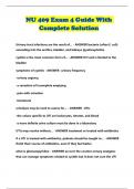
• The first diagram is a 2D picture of the field lines that surround a positive charge.
• Not shown are field lines going out of and into the page (3-D)
• The field lines radiate outwards because an electric field vector points in the direction of the force on a
positive test charge.
• The nearer you get to the charge, the stronger the field.
• Further away the field strength gets weaker, - the field lines become more spread out.
• Force, F on a charge, q in an electric field, E is: 𝐹 = 𝐸𝑞
3
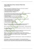
, The force that two-point charges, Q and q, separated by a distance r, exert on one another is given by:
𝐾𝑄𝑞
𝐹=
𝑟2
where K = 9 x 10⁹ Nm2/C2 (constant). This force represents the ability to perform work, showing that there is energy
in an electric field.
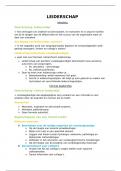
Capacitors
A parallel-plate capacitor is a common way to produce a uniform electric field: two flat, metal, parallel plates, one
negative, one positive. Aside from some fringing on the edges, the field is nearly uniform inside, meaning that
everywhere inside the capacitor, the field has approximately the same magnitude and direction. This electric field
stores energy.
• A capacitor typically consists of two metal plates separated by an insulator. The insulator between the plates
can either be a vacuum (air), or a dielectric material.
• When a capacitor is connected across a voltage source, charge flows between the source and the capacitor’s
plates until the voltage across the capacitor is equal to the source voltage
• In this process, one plate becomes positively charged, and the other plate becomes negatively charged
(electrons are drawn away from the positive plate)
• Capacitance, C is the measure of a capacitor’s ability to store charge, measured in Farad(F)
4
Contents
Week 1: Fundamentals ..................................................................................................................................................... 3
Charge, Electric Fields and Current ............................................................................................................................... 3
Fundamentals of Charge: Bohr’s Atomic Model ....................................................................................................... 3
Capacitors.................................................................................................................................................................. 4
Permittivity ................................................................................................................................................................ 5
Week 2: ............................................................................................................................................................................. 7
Magnetic Fields ........................................................................................................................................................... 10
Magnetic Field Fundamentals and Flux .................................................................................................................. 10
Magnetic Properties of Materials: .......................................................................................................................... 10
Magnetic Circuits .................................................................................................................................................... 12
Magnetic Field and Electromagnetics ......................................................................................................................... 13
Inductors ................................................................................................................................................................. 13
Transformers ........................................................................................................................................................... 15
Optics and Waves ........................................................................................................................................................ 17
Week 3: Symbols and Conventions in Electric Circuits ................................................................................................... 23
Voltage and Current .................................................................................................................................................... 23
Power and Energy ....................................................................................................................................................... 23
Mechanical Analogy of Ohm’s Law ............................................................................................................................. 23
Basic Active Circuit Elements ...................................................................................................................................... 24
Basic Convention ......................................................................................................................................................... 25
Week 3: Nodal Analysis for DC Circuits ........................................................................................................................... 26
Kirchhoff’s Current Law ............................................................................................................................................... 26
Nodal Analysis ............................................................................................................................................................. 26
Admittance Matrix ...................................................................................................................................................... 27
Mesh Analysis in DC Circuits ........................................................................................................................................... 27
Kirchhoff’s Voltage Law ............................................................................................................................................... 27
Mesh Analysis.............................................................................................................................................................. 28
Impedance Matrix ....................................................................................................................................................... 28
Week 4: Thevenin and Norton Circuits ........................................................................................................................... 29
Thevenin Equivalent Circuits ....................................................................................................................................... 29
Steps for calculating Thevenin Equivalent Circuits.................................................................................................. 29
Norton Equivalent Circuits .......................................................................................................................................... 30
Maximum Power Transfer ........................................................................................................................................... 30
1
,Week 5: RC Circuits ......................................................................................................................................................... 31
Definition of Capacitance ............................................................................................................................................ 31
Capacitor Charging Transient .................................................................................................................................. 31
Week 6: First Order RL Circuits and an Introduction to AC Circuits ................................................................................ 33
Current and Magnetism .............................................................................................................................................. 33
Definition of Inductance ............................................................................................................................................. 33
Mechanical Analogy of Inductance ............................................................................................................................. 34
Inductor Discharge ...................................................................................................................................................... 36
Step Response of an Inductor ..................................................................................................................................... 36
Week 6 (2): Alternating Current (AC) Circuits ................................................................................................................. 36
AC Voltages and Currents ............................................................................................................................................ 36
Reactance in AC Circuits .............................................................................................................................................. 37
Phasor Diagrams ..................................................................................................................................................... 38
Week 6: Alternating Circuits (AC) Circuits (2).................................................................................................................. 39
Complex Impedances .................................................................................................................................................. 39
2
,Week 1: Fundamentals
Charge, Electric Fields and Current
Charge is a fundamental property of matter – it can not be created or destroyed. Electrons have negative charge;
protons have an equal and opposite charge. Charged particles create a field around them, which has the capacity to
attract opposite charged particles and repel like-charged particles. Therefore, this field has energy (potential energy),
energy is defined as having the capacity to do work. This field is called an electric field, E measured in Volts/Metre.
• Charge (Q) – Measured in Coulomb, C
• Charge on an Electron = -1.6 x 10⁻¹⁹C
• Movement of charge, e.g. through a wire, gives an electric current, I
𝑄
• Current: Flow of charge per second 𝐼= 𝑡
• 1A is 1 coulomb or charge transferred in 1 second
Fundamentals of Charge: Bohr’s Atomic Model
• Niels Bohr proposed an atomic model that suggested that electrons orbit the nucleus, much like the Earth
revolving around the Sun.
• These orbitals (the path by which the electrons orbit the nucleus) have fixed distances and fixed energies.
• The orbitals closest to the nucleus have the lowest energy, and the orbitals furthest away from the nucleus
have the greatest energy (like a SPRING)
• An atom will usually have the same number of positives (protons) and negatives (electrons)
• This makes the atom NEUTRAL.
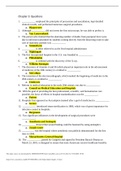
• The first diagram is a 2D picture of the field lines that surround a positive charge.
• Not shown are field lines going out of and into the page (3-D)
• The field lines radiate outwards because an electric field vector points in the direction of the force on a
positive test charge.
• The nearer you get to the charge, the stronger the field.
• Further away the field strength gets weaker, - the field lines become more spread out.
• Force, F on a charge, q in an electric field, E is: 𝐹 = 𝐸𝑞
3
, The force that two-point charges, Q and q, separated by a distance r, exert on one another is given by:
𝐾𝑄𝑞
𝐹=
𝑟2
where K = 9 x 10⁹ Nm2/C2 (constant). This force represents the ability to perform work, showing that there is energy
in an electric field.
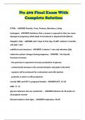
Capacitors
A parallel-plate capacitor is a common way to produce a uniform electric field: two flat, metal, parallel plates, one
negative, one positive. Aside from some fringing on the edges, the field is nearly uniform inside, meaning that
everywhere inside the capacitor, the field has approximately the same magnitude and direction. This electric field
stores energy.
• A capacitor typically consists of two metal plates separated by an insulator. The insulator between the plates
can either be a vacuum (air), or a dielectric material.
• When a capacitor is connected across a voltage source, charge flows between the source and the capacitor’s
plates until the voltage across the capacitor is equal to the source voltage
• In this process, one plate becomes positively charged, and the other plate becomes negatively charged
(electrons are drawn away from the positive plate)
• Capacitance, C is the measure of a capacitor’s ability to store charge, measured in Farad(F)
4