
PHYSICS NOTES 4U / DETAILED TOPIC SERIES
Capacitance and RC circuits
AQA 7408 | Detailed topic revision
Detailed topic pack / AQA 7408 section 3.7.4
A capacitor stores energy by separating charge. Its voltage changes as charge moves, so a
resistor-capacitor circuit cannot be treated as a steady-current resistor network throughout
charging or discharging. This pack connects the charge model to exponential graphs and
practical measurement.
Capacitance, parallel plates and dielectrics, stored energy, charge/discharge equations,
signed current, time constants, logarithmic analysis and required practical 9. Fourteen
original tasks with worked solutions.
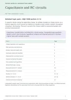
Find it Page
Charge separation and capacitance 2
Plate geometry and dielectrics 3
Energy / area and supply work 4
Discharge model and equations 5
Charging from a constant source 6
Original normalised RC graphs 7
Time constant and logarithms 8
Worked discharge / energy 9
Required practical 9 / method 10
Required practical 9 / analysis 11
Practice 1––14
Worked solutions 1––14
Checklist and source mapping 16
Independent revision notes, not produced or endorsed by AQA. Original examples and tasks, not official questions.
Apparatus descriptions are for supervised school work using approved low-voltage equipment.
Independent revision notes • Edition 1.0 for review • October 2026 1
,PHYSICS NOTES 4U / DETAILED TOPIC SERIES
Capacitance / what Q represents
AQA 7408 | Detailed topic revision
Capacitance C=Q/V, in farads (F).
Q is the magnitude of charge on either plate; V is potential difference between plates.
For an ideal fixed capacitor, Q=CV and C is constant, not a function of how much charge is
currently stored.
Charging transfers electrons from one plate to the other through the external circuit. Plates
carry equal opposite charges +Q and −Q; an initially neutral complete capacitor still has net
zero charge. “Charge stored Q” does not mean adding both plate magnitudes to make 2Q.
There is no steady conduction current across an ideal insulating gap.
Worked capacitance
A capacitor with 240 μC on each plate at 12 V has C=240×10−6/12=20 μF. At 6 V the same
capacitor has Q=120 μC; capacitance remains 20 μF provided geometry and dielectric
behaviour are unchanged.
Prefix Farads
mF / millifarad 10⁻³ F
μF / microfarad 10⁻⁶ F
nF / nanofarad 10⁻⁹ F
pF / picofarad 10⁻¹² F
A Q-V graph for fixed C is a straight line through the origin with gradient C. A V-Q graph has
gradient 1/C. Check which quantity is on each axis before interpreting the slope.
Real capacitors have voltage ratings, tolerance, leakage and sometimes polarity. A simple ideal model does not
remove those practical restrictions.
Independent revision notes • Edition 1.0 for review • October 2026 2
, PHYSICS NOTES 4U / DETAILED TOPIC SERIES
Parallel plates / dielectric action
AQA 7408 | Detailed topic revision
For overlapping area A, separation d and a uniform filling dielectric:
C=ε0εrA/d.
ε0≈8.85×10⁻¹² F m−1; εr is relative permittivity (dielectric constant), dimensionless.
Air/vacuum has εr approximately 1. Edge effects are neglected.
Greater overlap provides more charge-storage area; smaller separation gives a larger
capacitance. Use overlap area, not total outside dimensions if the plates overlap only partly.
This simple formula assumes separation is small compared with plate dimensions.
Polar molecules
A polar molecule has permanent separated positive and negative charge centres. An electric
field exerts a turning effect, tending to align its dipole with the field. Bound charges at dielectric
faces produce a field opposing the original plate field. Thermal motion prevents perfect
alignment; the simple linear model describes the overall response.
Insert dielectric fully Ideal consequence
Capacitor disconnected / fixed Q Net E and V decrease; C increases. Stored energy Q²/(2C)
decreases.
Source remains connected / fixed V Source supplies more charge as C increases. E≈V/d stays
fixed overall; stored energy ½CV² increases.
Worked geometry
A=0.020 m², d=0.50 mm and εr=3.0: C=8.85×10−12×3.0×0.020/(5.0×10−4)=1.06×10−9
F=1.06 nF.
In the disconnected case, energy changes can include mechanical work as the dielectric is pulled in. In the
connected case, include the source in the energy account.
Independent revision notes • Edition 1.0 for review • October 2026 3