

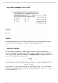
1: Calculate induced EMF in coil
Answer
(A) 2.4 V
Solution
To determine the magnitude of the induced electromotive force (EMF) in the coil, we apply
the principles of electromagnetism related to changing magnetic fields.
1. Governing Principle
The phenomenon of producing an EMF through a change in magnetic environment is
described by Faraday’s Law of Induction. It states that the magnitude of the induced EMF
(ℰ︀) in a circuit is equal to the rate of change of the magnetic flux (Φ𝐵 ) through the circuit. For
a coil with 𝑁 turns, the law is expressed as:
ΔΦ𝐵
ℰ︀ = 𝑁 | |
Δ𝑡
Where the magnetic flux Φ𝐵 through a single turn of area 𝐴 in a uniform magnetic field 𝐵 is:
Φ𝐵 = 𝐵 ⋅ 𝐴 ⋅ cos(𝜃)
In this problem, the coil is placed perpendicular to the magnetic field, meaning the angle 𝜃
between the magnetic field vector and the normal to the surface is 0∘ . Thus, cos(0∘ ) = 1, and
the flux simplifies to Φ𝐵 = 𝐵 ⋅ 𝐴.
,2. Identification of Given Parameters
From the problem description, we have the following values:
• Number of turns: 𝑁 = 100
• Area of the coil: 𝐴 = 0.02 m2
• Initial magnetic field: 𝐵1 = 0.2 T
• Final magnetic field: 𝐵2 = 0.8 T
• Time interval: Δ𝑡 = 0.5 s
3. Calculation of Induced EMF
First, we calculate the change in the magnetic field (Δ𝐵):
Δ𝐵 = 𝐵2 − 𝐵1
= 0.8 T − 0.2 T
= 0.6 T
Next, we substitute the parameters into the formula for the magnitude of the induced EMF:
, Δ𝐵
ℰ︀ = 𝑁 ⋅ 𝐴 ⋅
Δ𝑡
0.6 T
= 100 ⋅ 0.02 m2 ⋅
0.5 s
0.6 T
= 2 m2 ⋅
0.5 s
= 2 ⋅ 1.2 V
= 2.4 V
The magnitude of the induced EMF in the coil is calculated to be 2.4 V. Comparing this result
to the given options:
• (A) 2.4 V
• (B) 4.0 V
• (C) 6.0 V
• (D) 8.0 V
(𝐴) 2.4 𝑉
Answer
(A) 2.4 V
Solution
To determine the magnitude of the induced electromotive force (EMF) in the coil, we apply
the principles of electromagnetism related to changing magnetic fields.
1. Governing Principle
The phenomenon of producing an EMF through a change in magnetic environment is
described by Faraday’s Law of Induction. It states that the magnitude of the induced EMF
(ℰ︀) in a circuit is equal to the rate of change of the magnetic flux (Φ𝐵 ) through the circuit. For
a coil with 𝑁 turns, the law is expressed as:
ΔΦ𝐵
ℰ︀ = 𝑁 | |
Δ𝑡
Where the magnetic flux Φ𝐵 through a single turn of area 𝐴 in a uniform magnetic field 𝐵 is:
Φ𝐵 = 𝐵 ⋅ 𝐴 ⋅ cos(𝜃)
In this problem, the coil is placed perpendicular to the magnetic field, meaning the angle 𝜃
between the magnetic field vector and the normal to the surface is 0∘ . Thus, cos(0∘ ) = 1, and
the flux simplifies to Φ𝐵 = 𝐵 ⋅ 𝐴.
,2. Identification of Given Parameters
From the problem description, we have the following values:
• Number of turns: 𝑁 = 100
• Area of the coil: 𝐴 = 0.02 m2
• Initial magnetic field: 𝐵1 = 0.2 T
• Final magnetic field: 𝐵2 = 0.8 T
• Time interval: Δ𝑡 = 0.5 s
3. Calculation of Induced EMF
First, we calculate the change in the magnetic field (Δ𝐵):
Δ𝐵 = 𝐵2 − 𝐵1
= 0.8 T − 0.2 T
= 0.6 T
Next, we substitute the parameters into the formula for the magnitude of the induced EMF:
, Δ𝐵
ℰ︀ = 𝑁 ⋅ 𝐴 ⋅
Δ𝑡
0.6 T
= 100 ⋅ 0.02 m2 ⋅
0.5 s
0.6 T
= 2 m2 ⋅
0.5 s
= 2 ⋅ 1.2 V
= 2.4 V
The magnitude of the induced EMF in the coil is calculated to be 2.4 V. Comparing this result
to the given options:
• (A) 2.4 V
• (B) 4.0 V
• (C) 6.0 V
• (D) 8.0 V
(𝐴) 2.4 𝑉

