2025 AQA A-Level PHYSICS 7408/3BC
Paper 3 Section B Engineering physics
Question paper and Marking scheme Merged
Please write clearly in block capitals.
Centre number Candidate number
Surname
Forename(s)
Candidate signature
I declare this is my own work.
A-level
PHYSICS
Paper 3
Section B Engineering physics
Tuesday 17 June 2025 Morning Time allowed: The total time for
both sections of this paper is
Materials
2 hours. You are advised to
For this paper you must have:
• a pencil and a ruler spend approximately
• a scientific calculator 50 minutes on this section.
• a Data and Formulae Booklet
• a protractor.
Instructions For Examiner’s Use
• Use black ink or black ball-point pen.
Question Mark
• Fill in the boxes at the top of this page.
• Answer all questions. 1
• You must answer the questions in the spaces provided. Do not write 2
outside the box around each page or on blank pages. 3 IB/M/Jun25/G4
• If you need extra space for your answer(s), use the lined pages at the end of
4
this book. Write the question number against your answer(s).
• Do all rough work in this book. Cross through any work you do not want TOTAL
to be marked.
• Show all your working.
Information
• The marks for questions are shown in brackets.
• The maximum mark for this paper is 35.
• You are expected to use a scientific calculator where appropriate.
• A Data and Formulae Booklet is provided as a loose insert.
, 2
Do not write
outside the
Section B box
Answer all questions in this section.
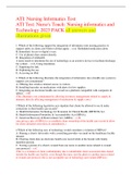
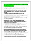
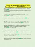
0 1 The rotating part of an electric motor is called the rotor.
Figure 1 shows an end view of a rotor turning clockwise due to a driving torque from
the motor. In this question, the clockwise direction is treated as positive.
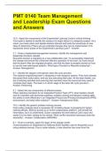
Figure 1 Figure 2
The rotor can be brought to rest rapidly by reversing the electrical supply connections
to the motor. Figure 2 shows the rotor at time t = 0 when the supply connections are
reversed.
The rotor then slows down due to a constant anticlockwise retarding torque so that it
stops at time t = t1.
The angular velocity of the rotor at t = 0 is 98.0 rad s−1 clockwise.
The applied torque on the rotor at t = 0 is anticlockwise.
The applied torque produces a constant angular acceleration of −303 rad s−2.
Friction torque is negligible.
0 1 . 1 Determine t1.
[2 marks]
t1 = s
for more: tyrionpapers.com
IB/M/Jun25/7408/3BC
, 3
Do not write
outside the
box
The electrical supply remains connected and the rotor now accelerates uniformly
anticlockwise with an acceleration of magnitude 303 rad s−2.
At a later time t = t2, the angular velocity of the rotor is −120 rad s−1.
0 1 . 2 Determine the number of anticlockwise revolutions made by the rotor between
t1 and t2.
[2 marks]
number of revolutions =
0 1 . 3 The moment of inertia of the rotor about the axis of rotation is 9.60 × 10⁻² kg m2.
Calculate the angular impulse on the rotor between t = 0 and t2.
[1 mark]
angular impulse = Nms
Question 1 continues on the next page
Turn over ►
for more: tyrionpapers.com
IB/M/Jun25/7408/3BC
, 4
Do not write
outside the
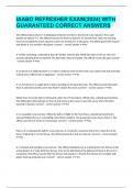
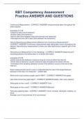
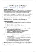
0 1 . 4 Another way of quickly stopping the motor is to use a disc brake. The motor is box
brought to rest by switching off the power supply and then forcing two brake pads
against the disc.
Figure 3 shows the two brake pads each applying a constant retarding force of 182 N
to the disc.
Figure 3
moment of inertia of rotor and disc about the axis of rotation = 0.101 kg m2
diameter of disc = 0.160 m
diameter of pad = 22 mm
Compare the angular deceleration produced by the disc brake system with the
angular deceleration produced by reversing the electrical connections.
[3 marks]
8
for more: tyrionpapers.com
IB/M/Jun25/7408/3BC
Paper 3 Section B Engineering physics
Question paper and Marking scheme Merged
Please write clearly in block capitals.
Centre number Candidate number
Surname
Forename(s)
Candidate signature
I declare this is my own work.
A-level
PHYSICS
Paper 3
Section B Engineering physics
Tuesday 17 June 2025 Morning Time allowed: The total time for
both sections of this paper is
Materials
2 hours. You are advised to
For this paper you must have:
• a pencil and a ruler spend approximately
• a scientific calculator 50 minutes on this section.
• a Data and Formulae Booklet
• a protractor.
Instructions For Examiner’s Use
• Use black ink or black ball-point pen.
Question Mark
• Fill in the boxes at the top of this page.
• Answer all questions. 1
• You must answer the questions in the spaces provided. Do not write 2
outside the box around each page or on blank pages. 3 IB/M/Jun25/G4
• If you need extra space for your answer(s), use the lined pages at the end of
4
this book. Write the question number against your answer(s).
• Do all rough work in this book. Cross through any work you do not want TOTAL
to be marked.
• Show all your working.
Information
• The marks for questions are shown in brackets.
• The maximum mark for this paper is 35.
• You are expected to use a scientific calculator where appropriate.
• A Data and Formulae Booklet is provided as a loose insert.
, 2
Do not write
outside the
Section B box
Answer all questions in this section.
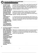
0 1 The rotating part of an electric motor is called the rotor.
Figure 1 shows an end view of a rotor turning clockwise due to a driving torque from
the motor. In this question, the clockwise direction is treated as positive.
Figure 1 Figure 2
The rotor can be brought to rest rapidly by reversing the electrical supply connections
to the motor. Figure 2 shows the rotor at time t = 0 when the supply connections are
reversed.
The rotor then slows down due to a constant anticlockwise retarding torque so that it
stops at time t = t1.
The angular velocity of the rotor at t = 0 is 98.0 rad s−1 clockwise.
The applied torque on the rotor at t = 0 is anticlockwise.
The applied torque produces a constant angular acceleration of −303 rad s−2.
Friction torque is negligible.
0 1 . 1 Determine t1.
[2 marks]
t1 = s
for more: tyrionpapers.com
IB/M/Jun25/7408/3BC
, 3
Do not write
outside the
box
The electrical supply remains connected and the rotor now accelerates uniformly
anticlockwise with an acceleration of magnitude 303 rad s−2.
At a later time t = t2, the angular velocity of the rotor is −120 rad s−1.
0 1 . 2 Determine the number of anticlockwise revolutions made by the rotor between
t1 and t2.
[2 marks]
number of revolutions =
0 1 . 3 The moment of inertia of the rotor about the axis of rotation is 9.60 × 10⁻² kg m2.
Calculate the angular impulse on the rotor between t = 0 and t2.
[1 mark]
angular impulse = Nms
Question 1 continues on the next page
Turn over ►
for more: tyrionpapers.com
IB/M/Jun25/7408/3BC
, 4
Do not write
outside the
0 1 . 4 Another way of quickly stopping the motor is to use a disc brake. The motor is box
brought to rest by switching off the power supply and then forcing two brake pads
against the disc.
Figure 3 shows the two brake pads each applying a constant retarding force of 182 N
to the disc.
Figure 3
moment of inertia of rotor and disc about the axis of rotation = 0.101 kg m2
diameter of disc = 0.160 m
diameter of pad = 22 mm
Compare the angular deceleration produced by the disc brake system with the
angular deceleration produced by reversing the electrical connections.
[3 marks]
8
for more: tyrionpapers.com
IB/M/Jun25/7408/3BC