ALL CHAPTERS COVERED
SOLUTIONS MANUAL
,1 Characteristics of Aircraft Structures and Materials
2 Loads on Aircraft Structures
3 Introduction to Elasticity
4 Torsion
5 Bending and Flexural Shear
6 Flexural Shear Flow in Thin‐Walled Sections
7 Failure Criteria for Isotropic Materials
8 Elastic Buckling
9 Analysis of Composite Laminates
,Name: Mohamed Naleer Abdul Gaffor Email: IP: 184.162.144.24
Mechanics of Aircraft structures
C.T. Sun
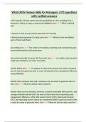
1.1 The beam of a rectangular thin-walled section (i.e., t is very small) is designed
to carry both bending moment M and torque T. If the total wall contour length
L = 2( a + b) (see Fig. 1.16) is fixed, find the optimum b/a ratio to achieve the
most efficient section if M = T and σ allowable = 2τ allowable . Note that for closed
thin-walled sections such as the one in Fig.1.16, the shear stress due to torsion is
T
τ=
2abt
Figure 1.16 Closed thin-walled section
Solution:
My
(1) The bending stress of beams is σ = , where y is the distance from the neutral
I
axis. The moment of inertia I of the cross-section can be calculated by considering
the four segments of thin walls and using the formula for a rectangular section
1
with height h and width w. I = ∑ ( wh 3 + Ad 2 ) in which A is the
12
cross-sectional area of the segment and d is the distance of the centroid of the
segment to the neutral axis. Note that the Parallel Axis Theorem is applied. The
1 3 1 b tb 2
result is I = 2 ⋅ tb + 2 ⋅ [ ⋅ at 3 + (at ) ⋅ ( ) 2 ] ≈ (3a + b) , assuming that t is
12 12 2 6
very small.
(2) The shear stress due to torsion for a closed thin-walled section shown above is
T
τ= .
2abt
1.1.1
Address: 1650, BLVD DE MAISONNEUVE Apt. 904, Montreal, QC H3H2P3, CAN
,Name: Mohamed Naleer Abdul Gaffor Email: IP: 184.162.144.24
Mechanics of Aircraft structures
C.T. Sun
(3) Two approaches are employed to find the solution.
(i) Assume that the bending stress reaches the allowable σ allowable first and find
the corresponding bending maximum bending moment. Then apply the stated
loading condition of T = M to check whether the corresponding τ max has
exceeded the allowable shear stress τ allowable . If this condition is violated, then
the optimized b/a ratio is not valid.
b
M⋅
My 2 3M
(a) σ | b = = 2 =
y= I tb tb(3a + b)
2
(3a + b)
6
When given L = 2( a + b) as a constant, a can be expressed in terms of b
L
and L as a = − b . Then we can minimize
2
tb(3a + b) tb(3L − 4b)
S= = in order to maximize σ , i.e.,
3 6
∂S t 3L L L
= 0 ⇒ (3L − 8b) = 0 ⇒ b = , so a = − b =
∂b 6 8 2 8
b
where the optimum ratio is =3
a
3M 3M 32M
Thus, σ max = = =
tb(3a + b) t ⋅ (3L / 8) ⋅ (3 ⋅ L / 8 + 3L / 8) 3tL2
(b) Check τ max with T = M and b/a = 3 and check whether τ max is within
the allowable shear stress τ allowable .
T M 32M
τ max = = = = σ max = σ allowable
2abt 2 ⋅ ( L / 8) ⋅ (3L / 8) ⋅ t 3tL2
σ allowable
> τ allowable =
2
The result above means that under this assumption, shear stress τ would
reach the allowable stress τ allowable before σ reaches σ allowable . Consequently,
the optimal ratio obtained is not valid and different assumption needs to be
made.
(ii) Assume now that failure is controlled by shear stress. We assume that
τ max = τ allowable is reached first and then find the corresponding bending stress
according to the loading condition M = T .
T
(a) τ =
2abt
Again we minimize S = 2abt = ( L − 2b)bt in order to maximize τ , i.e.,
1.1.2
Address: 1650, BLVD DE MAISONNEUVE Apt. 904, Montreal, QC H3H2P3, CAN
SOLUTIONS MANUAL
,1 Characteristics of Aircraft Structures and Materials
2 Loads on Aircraft Structures
3 Introduction to Elasticity
4 Torsion
5 Bending and Flexural Shear
6 Flexural Shear Flow in Thin‐Walled Sections
7 Failure Criteria for Isotropic Materials
8 Elastic Buckling
9 Analysis of Composite Laminates
,Name: Mohamed Naleer Abdul Gaffor Email: IP: 184.162.144.24
Mechanics of Aircraft structures
C.T. Sun
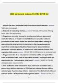
1.1 The beam of a rectangular thin-walled section (i.e., t is very small) is designed
to carry both bending moment M and torque T. If the total wall contour length
L = 2( a + b) (see Fig. 1.16) is fixed, find the optimum b/a ratio to achieve the
most efficient section if M = T and σ allowable = 2τ allowable . Note that for closed
thin-walled sections such as the one in Fig.1.16, the shear stress due to torsion is
T
τ=
2abt
Figure 1.16 Closed thin-walled section
Solution:
My
(1) The bending stress of beams is σ = , where y is the distance from the neutral
I
axis. The moment of inertia I of the cross-section can be calculated by considering
the four segments of thin walls and using the formula for a rectangular section
1
with height h and width w. I = ∑ ( wh 3 + Ad 2 ) in which A is the
12
cross-sectional area of the segment and d is the distance of the centroid of the
segment to the neutral axis. Note that the Parallel Axis Theorem is applied. The
1 3 1 b tb 2
result is I = 2 ⋅ tb + 2 ⋅ [ ⋅ at 3 + (at ) ⋅ ( ) 2 ] ≈ (3a + b) , assuming that t is
12 12 2 6
very small.
(2) The shear stress due to torsion for a closed thin-walled section shown above is
T
τ= .
2abt
1.1.1
Address: 1650, BLVD DE MAISONNEUVE Apt. 904, Montreal, QC H3H2P3, CAN
,Name: Mohamed Naleer Abdul Gaffor Email: IP: 184.162.144.24
Mechanics of Aircraft structures
C.T. Sun
(3) Two approaches are employed to find the solution.
(i) Assume that the bending stress reaches the allowable σ allowable first and find
the corresponding bending maximum bending moment. Then apply the stated
loading condition of T = M to check whether the corresponding τ max has
exceeded the allowable shear stress τ allowable . If this condition is violated, then
the optimized b/a ratio is not valid.
b
M⋅
My 2 3M
(a) σ | b = = 2 =
y= I tb tb(3a + b)
2
(3a + b)
6
When given L = 2( a + b) as a constant, a can be expressed in terms of b
L
and L as a = − b . Then we can minimize
2
tb(3a + b) tb(3L − 4b)
S= = in order to maximize σ , i.e.,
3 6
∂S t 3L L L
= 0 ⇒ (3L − 8b) = 0 ⇒ b = , so a = − b =
∂b 6 8 2 8
b
where the optimum ratio is =3
a
3M 3M 32M
Thus, σ max = = =
tb(3a + b) t ⋅ (3L / 8) ⋅ (3 ⋅ L / 8 + 3L / 8) 3tL2
(b) Check τ max with T = M and b/a = 3 and check whether τ max is within
the allowable shear stress τ allowable .
T M 32M
τ max = = = = σ max = σ allowable
2abt 2 ⋅ ( L / 8) ⋅ (3L / 8) ⋅ t 3tL2
σ allowable
> τ allowable =
2
The result above means that under this assumption, shear stress τ would
reach the allowable stress τ allowable before σ reaches σ allowable . Consequently,
the optimal ratio obtained is not valid and different assumption needs to be
made.
(ii) Assume now that failure is controlled by shear stress. We assume that
τ max = τ allowable is reached first and then find the corresponding bending stress
according to the loading condition M = T .
T
(a) τ =
2abt
Again we minimize S = 2abt = ( L − 2b)bt in order to maximize τ , i.e.,
1.1.2
Address: 1650, BLVD DE MAISONNEUVE Apt. 904, Montreal, QC H3H2P3, CAN