Please write clearly in block capitals.
Centre number Candidate number
Surname
Forename(s)
Candidate signatu re
I declare this is my own work.
A-level 2024_AQA A-Level Physics
PHYSICS Paper 3
Section B Electronics
(Merged Question Paper and Marking Scheme)
Paper 3 Monday 17 June 2024
Section B Electronics
Monday 17 June 2024 Morning Time allowed: The total time for
Materials
both sections of this paper is
For this paper you must have: 2 hours. You are advised to
a pencil and a ruler spend approximately
a scientific calculator
a Data and Formulae Booklet 50 minutes on this section.
a protractor.
For Examiner’s Use
Instructions
Use black ink or black ball-point pen. Question Mark
Fill in the boxes at the top of this page. 1
Answer all questions.
2
You must answer the questions in the spaces provided. Do not write
outside the box around each page or on blank pages. 3
If you need extra space for your answer(s), use the lined pages at the end of 4
this book. Write the question number against your answer(s). 5
Do all rough work in this book. Cross through any work you do not want
to be marked. TOTAL
Show all your working.
Information
The marks for questions are shown in brackets.
The maximum mark for this paper is 35.
You are expected to use a scientific calculator where appropriate.
A Data and Formulae Booklet is provided as a loose insert.
, IB/M/Jun24/E8
A-Level Physics: Paper 3 Section B – Electronics: Exam Review Question
Section B of Paper 3 focuses on Electronics, which covers the application of
physics in the design and functioning of electronic circuits and devices. It
includes components such as diodes, transistors, capacitors, and their use in
amplification, rectification, and digital systems.
1. Semiconductor Physics:
7408/3BE
Semiconductors: Understand the properties of semiconductors (like
silicon and germanium) and how they are used to control the flow of
electrical current. Review the difference between conductors,
insulators, and semiconductors.
Intrinsic and Extrinsic Semiconductors: Learn about intrinsic
semiconductors (pure materials) and extrinsic semiconductors
(doped materials), and how doping adds n-type (negative) or p-type
(positive) carriers to the semiconductor.
Energy Bands: Study the concept of energy bands in solids,
particularly the valence band and conduction band, and the role of
the band gap in determining whether a material is a conductor,
semiconductor, or insulator.
2. Diodes and Rectification:
Diodes: Understand the function of a diode in electronic circuits. A
diode allows current to flow in one direction only, acting as a rectifier.
Forward and Reverse Bias: Learn the behavior of diodes under
forward bias (current flows) and reverse bias (no current flow).
Rectification: Study how diodes are used in rectifier circuits to
convert alternating current (AC) to direct current (DC). 3. Transistors
and Amplification:
4. Capacitors in Electronics:
Capacitors: Understand the function of capacitors, which store electrical
energy in an electric field. Learn how they are used in circuits to smooth
out voltage fluctuations (in power supplies) and in timing applications
(e.g., RC circuits).
Capacitance:
5. Key Concepts to Revise:
Semiconductor Behavior: Understand doping, energy bands, and the
properties of n-type and p-type semiconductors.
Diodes and Rectification: Review how diodes work in rectifier circuits
and how rectification transforms AC into DC.
Transistors: Focus on the operation of BJTs and FETs, and how they
are used in amplification and switching.
o Capacitors: Understand the role of capacitors in smoothing voltages
and timing applications, and be familiar with RC circuits.
o Digital Logic: Be able to analyze and simplify logic circuits, and
understand the use of logic gates in digital electronics.
o Power Supply Circuits: Review the conversion of AC to DC power,
including rectifiers, filters, and regulators.
, 2
Do not write
outside the
Section B box
Answer all questions in this section.
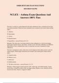
0 1 A toy manufacturer is designing a two-tone siren for use in small battery-operated
cars.
Figure 1 shows design Option 1.
Option 1 uses three separate signal generators feeding into a logic sub-system.
The signal generators produce logic-compatible 9 V square waves of frequencies
1024 Hz, 1 Hz and 512 Hz.
Figure 1
The waveforms shown are not to scale.
0 1
. 1 Explain how the logic level applied at B in Figure 1 determines the output frequency
at Q.
[2 marks]
0 1 . 2 Write the Boolean algebra expression for output Q in terms of the inputs A, B and C.
Use only the logic operations shown in Figure 1.
[2 marks]
Q=
IB/M/Jun24/7408/3BE
, 3
Do not write
outside the
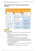
0 1 . 3 Option 1 is tested by replacing the 1 Hz signal generator with a manual input. box
The manual input is provided by the combination of a push-to-make switch
and a 10 kΩ resistor.
The combination produces the following voltages at its output:
0 V when the switch is not pressed
9 V when the switch is pressed.
Figure 2 shows the symbol for the push-to-make switch.
Figure 2
Complete Figure 3 to show how this switch and the 10 kΩ resistor are connected.
Label the output Vout.
You do not need to add details taken from Figure 1.
[1 mark]
Figure 3
Question 1 continues on the next page
Turn over ►
IB/M/Jun24/7408/3BE
, 4
Do not write
outside the
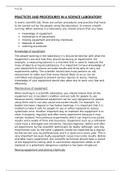
0 1 . 4 Figure 4 shows a generalised layout of an integrated circuit (IC) for an N-bit binary box
counter.
Q0 is the output that provides the least significant bit.
Figure 4
A signal generator feeds a square wave of frequency 1024 Hz into the clock of the IC.
The N-bit binary counter generates the 512 Hz signal and the 1 Hz signal from
separate outputs.
Deduce which of the outputs Q0 to QN will provide the 1 Hz signal.
[1 mark]
IB/M/Jun24/7408/3BE
, 5
Do not write
outside the
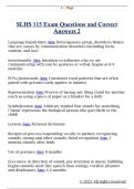
0 1 . 5 To make the two-tone siren, the manufacturer decides to use a new design, Option 2. box
Option 2 contains:
one 1024 Hz signal generator
one N-bit binary counter
a new logic sub-system as shown in Figure 5.
Figure 5
Assume that:
each type of logic gate has its own dedicated IC chip
each separate signal generator is based upon its own IC chip.
Compare the number of ICs used in Option 1 with the number used in Option 2.
Go on to explain one advantage of the manufacturer’s decision.
[2 marks]
8
Turn over ►
IB/M/Jun24/7408/3BE
, 6
Do not write
outside the
0 2 The short message service (SMS) on a mobile phone can send a maximum box
of 160 characters per message. Each character is represented by its own seven-bit
binary code as it is converted to digital data.
0 2
. 1 The mobile phone transmits digital data at a rate of 8 kilobytes per second (kB s−1)
when using the SMS function.
Determine the minimum time required to send 160 characters.
[2 marks]
time = s
Electrical noise can affect communication systems.
0 2
. 2 Describe one origin of electrical noise in a communication system.
[1 mark]
0 2 . 3 Describe the effect that electrical noise can have:
on the signal and
on the communication system.
[2 marks]
IB/M/Jun24/7408/3BE
, 7
Do not write
outside the
box
Figure 6 shows a noisy digital signal Vin which is applied to a circuit.
The circuit output Vout switches to:
5 V when the input voltage Vin falls below 1.8 V
0 V when the input voltage Vin rises above 3.2 V.
0 2
. 4 Draw, on Figure 7, the output signal Vout from the circuit.
Assume that Vout is initially at 5 V.
[2 marks] 7
Turn over ►
IB/M/Jun24/7408/3BE
Centre number Candidate number
Surname
Forename(s)
Candidate signatu re
I declare this is my own work.
A-level 2024_AQA A-Level Physics
PHYSICS Paper 3
Section B Electronics
(Merged Question Paper and Marking Scheme)
Paper 3 Monday 17 June 2024
Section B Electronics
Monday 17 June 2024 Morning Time allowed: The total time for
Materials
both sections of this paper is
For this paper you must have: 2 hours. You are advised to
a pencil and a ruler spend approximately
a scientific calculator
a Data and Formulae Booklet 50 minutes on this section.
a protractor.
For Examiner’s Use
Instructions
Use black ink or black ball-point pen. Question Mark
Fill in the boxes at the top of this page. 1
Answer all questions.
2
You must answer the questions in the spaces provided. Do not write
outside the box around each page or on blank pages. 3
If you need extra space for your answer(s), use the lined pages at the end of 4
this book. Write the question number against your answer(s). 5
Do all rough work in this book. Cross through any work you do not want
to be marked. TOTAL
Show all your working.
Information
The marks for questions are shown in brackets.
The maximum mark for this paper is 35.
You are expected to use a scientific calculator where appropriate.
A Data and Formulae Booklet is provided as a loose insert.
, IB/M/Jun24/E8
A-Level Physics: Paper 3 Section B – Electronics: Exam Review Question
Section B of Paper 3 focuses on Electronics, which covers the application of
physics in the design and functioning of electronic circuits and devices. It
includes components such as diodes, transistors, capacitors, and their use in
amplification, rectification, and digital systems.
1. Semiconductor Physics:
7408/3BE
Semiconductors: Understand the properties of semiconductors (like
silicon and germanium) and how they are used to control the flow of
electrical current. Review the difference between conductors,
insulators, and semiconductors.
Intrinsic and Extrinsic Semiconductors: Learn about intrinsic
semiconductors (pure materials) and extrinsic semiconductors
(doped materials), and how doping adds n-type (negative) or p-type
(positive) carriers to the semiconductor.
Energy Bands: Study the concept of energy bands in solids,
particularly the valence band and conduction band, and the role of
the band gap in determining whether a material is a conductor,
semiconductor, or insulator.
2. Diodes and Rectification:
Diodes: Understand the function of a diode in electronic circuits. A
diode allows current to flow in one direction only, acting as a rectifier.
Forward and Reverse Bias: Learn the behavior of diodes under
forward bias (current flows) and reverse bias (no current flow).
Rectification: Study how diodes are used in rectifier circuits to
convert alternating current (AC) to direct current (DC). 3. Transistors
and Amplification:
4. Capacitors in Electronics:
Capacitors: Understand the function of capacitors, which store electrical
energy in an electric field. Learn how they are used in circuits to smooth
out voltage fluctuations (in power supplies) and in timing applications
(e.g., RC circuits).
Capacitance:
5. Key Concepts to Revise:
Semiconductor Behavior: Understand doping, energy bands, and the
properties of n-type and p-type semiconductors.
Diodes and Rectification: Review how diodes work in rectifier circuits
and how rectification transforms AC into DC.
Transistors: Focus on the operation of BJTs and FETs, and how they
are used in amplification and switching.
o Capacitors: Understand the role of capacitors in smoothing voltages
and timing applications, and be familiar with RC circuits.
o Digital Logic: Be able to analyze and simplify logic circuits, and
understand the use of logic gates in digital electronics.
o Power Supply Circuits: Review the conversion of AC to DC power,
including rectifiers, filters, and regulators.
, 2
Do not write
outside the
Section B box
Answer all questions in this section.
0 1 A toy manufacturer is designing a two-tone siren for use in small battery-operated
cars.
Figure 1 shows design Option 1.
Option 1 uses three separate signal generators feeding into a logic sub-system.
The signal generators produce logic-compatible 9 V square waves of frequencies
1024 Hz, 1 Hz and 512 Hz.
Figure 1
The waveforms shown are not to scale.
0 1
. 1 Explain how the logic level applied at B in Figure 1 determines the output frequency
at Q.
[2 marks]
0 1 . 2 Write the Boolean algebra expression for output Q in terms of the inputs A, B and C.
Use only the logic operations shown in Figure 1.
[2 marks]
Q=
IB/M/Jun24/7408/3BE
, 3
Do not write
outside the
0 1 . 3 Option 1 is tested by replacing the 1 Hz signal generator with a manual input. box
The manual input is provided by the combination of a push-to-make switch
and a 10 kΩ resistor.
The combination produces the following voltages at its output:
0 V when the switch is not pressed
9 V when the switch is pressed.
Figure 2 shows the symbol for the push-to-make switch.
Figure 2
Complete Figure 3 to show how this switch and the 10 kΩ resistor are connected.
Label the output Vout.
You do not need to add details taken from Figure 1.
[1 mark]
Figure 3
Question 1 continues on the next page
Turn over ►
IB/M/Jun24/7408/3BE
, 4
Do not write
outside the
0 1 . 4 Figure 4 shows a generalised layout of an integrated circuit (IC) for an N-bit binary box
counter.
Q0 is the output that provides the least significant bit.
Figure 4
A signal generator feeds a square wave of frequency 1024 Hz into the clock of the IC.
The N-bit binary counter generates the 512 Hz signal and the 1 Hz signal from
separate outputs.
Deduce which of the outputs Q0 to QN will provide the 1 Hz signal.
[1 mark]
IB/M/Jun24/7408/3BE
, 5
Do not write
outside the
0 1 . 5 To make the two-tone siren, the manufacturer decides to use a new design, Option 2. box
Option 2 contains:
one 1024 Hz signal generator
one N-bit binary counter
a new logic sub-system as shown in Figure 5.
Figure 5
Assume that:
each type of logic gate has its own dedicated IC chip
each separate signal generator is based upon its own IC chip.
Compare the number of ICs used in Option 1 with the number used in Option 2.
Go on to explain one advantage of the manufacturer’s decision.
[2 marks]
8
Turn over ►
IB/M/Jun24/7408/3BE
, 6
Do not write
outside the
0 2 The short message service (SMS) on a mobile phone can send a maximum box
of 160 characters per message. Each character is represented by its own seven-bit
binary code as it is converted to digital data.
0 2
. 1 The mobile phone transmits digital data at a rate of 8 kilobytes per second (kB s−1)
when using the SMS function.
Determine the minimum time required to send 160 characters.
[2 marks]
time = s
Electrical noise can affect communication systems.
0 2
. 2 Describe one origin of electrical noise in a communication system.
[1 mark]
0 2 . 3 Describe the effect that electrical noise can have:
on the signal and
on the communication system.
[2 marks]
IB/M/Jun24/7408/3BE
, 7
Do not write
outside the
box
Figure 6 shows a noisy digital signal Vin which is applied to a circuit.
The circuit output Vout switches to:
5 V when the input voltage Vin falls below 1.8 V
0 V when the input voltage Vin rises above 3.2 V.
0 2
. 4 Draw, on Figure 7, the output signal Vout from the circuit.
Assume that Vout is initially at 5 V.
[2 marks] 7
Turn over ►
IB/M/Jun24/7408/3BE