2024_AQA A-Level Physics
Paper 3 Section A
(Merged Question Paper and Marking Scheme)
Monday 17 June 2024
Please write clearly in block capitals.
Centre number Candidate number
Surname
Forename(s)
Candidate signat ure
I declare this is my own work.
A-level
PHYSICS
Paper 3
Section A
Monday 17 June 2024 Morning Time allowed: The total time for
Materials
both sections of this paper is
For this paper you must have: 2 hours. You are advised to
a pencil and a ruler spend approximately
a scientific calculator
a Data and Formulae Booklet 70 minutes on this section.
a protractor.
For Examiner’s Use
Instructions
Question Mark
Use black ink or black ball-point pen.
Fill in the boxes at the top of this page. 1
Answer all questions. 2
You must answer the questions in the spaces provided. Do not write 3
outside the box around each page or on blank pages.
If you need extra space for your answer(s), use the lined pages at the end of TOTAL
this book. Write the question number against your answer(s). IB/M/Jun24/G4005/E9
Do all rough work in this book. Cross through any work you do not want
to be marked.
Show all your working.
Information
The marks for questions are shown in brackets.
The maximum mark for this paper is 45.
You are expected to use a scientific calculator where appropriate.
A Data and Formulae Booklet is provided as a loose insert.
,A-Level Physics: Paper 3 Section A: Exam Preview sections
This paper focuses on practical applications and investigations related to the
physics topics you have studied. Section A typically tests your ability to design
experiments, analyze data, and apply theoretical knowledge in practical
contexts.
7408/3A
1. Practical Skills and Investigations:
Experimental Design: You may be asked to design an experiment to
investigate a specific physical principle (e.g., measuring the acceleration
due to gravity, investigating Ohm's Law, or determining the Young's
modulus of a material).
o Key components to consider: variables (independent,
dependent, controlled), methods, safety, and equipment.
Data Analysis: Be prepared to interpret experimental data. This could
involve using graphical methods (e.g., plotting graphs, finding gradients,
and interpreting intercepts) and mathematical methods (e.g., calculating
uncertainty, error propagation, and using appropriate formulae).
Uncertainty and Error: You’ll need to calculate uncertainties in
measurements, including absolute and percentage uncertainty, and
explain how to minimize errors in experiments. Understand how to
report uncertainties when presenting results.
Practical Applications: You could be asked about the practical use of
physical principles in real-world situations (e.g., how materials with
different elastic properties are used in engineering or how radioactivity is
measured in a medical context).
2. Key Topics for Practical Investigation:
Mechanics:
o Investigating motion using different methods (e.g., measuring
velocity, acceleration, or forces in various setups).
o Understanding force and momentum through experiments with
colliding objects or measuring forces in systems like pulleys or
springs.
Electricity:
o Setting up circuits to investigate Ohm’s Law, the relationship
between voltage, current, and resistance in components
(resistors, thermistors, diodes, etc.).
o Experimenting with Kirchhoff’s laws to analyze complex
circuits.
Waves:
o Investigating wave properties such as wavelength, frequency,
and velocity using apparatus like a ripple tank or oscilloscopes.
o Experiments to demonstrate interference and diffraction,
especially for light and sound waves.
Materials:
o Testing the elastic properties of materials, including how to
determine the Young’s modulus of a material through stretching
experiments.
o Investigating the stress-strain relationship and applying it to real
materials like rubber or metal wires.
, 2
Do not write
outside the
Section A box
Answer all questions in this section.
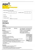
0 1 This question is based on a method to determine the resistivity of a wire (required
practical activity 5).
Figure 1 shows a micrometer screw gauge.
Figure 1
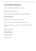
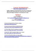
Figure 2 shows an enlarged view of the scales.
Figure 2
IB/M/Jun24/7408/3A
, 3
Do not write
outside the
0 1 . 1 State, in mm, the resolution of the main scale. box
[1 mark]
resolution = mm
0 1 . 2 What is the reading on the micrometer?
Tick (🗸) one box.
[1 mark]
6.22 mm
6.72 mm
6.78 mm
8.22 mm
0 1
. 3 A wire X is placed in the gap between the anvil and the spindle.
State and explain how this gap is closed just before taking a reading of the diameter
of X.
[1 mark]
Question 1 continues on the next page
Turn over ►
IB/M/Jun24/7408/3A
, 4
Do not write
outside the
box
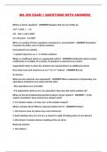
Figure 3 shows a circuit used to determine the resistance per metre of wire X.
Figure 3
Two terminals are used to mount X on a ruler.
Clips are used to connect a voltmeter across the 1.2 Ω resistor.
When the switch is closed, the voltmeter reading is 931 mV.
The switch is then opened and the voltmeter is connected to X as shown in Figure 4.
Figure 4
IB/M/Jun24/7408/3A
, 5
Do not write
outside the
0 1 . 4 When the switch is closed, the voltmeter reading is 397 mV. box
Show that, for the arrangement in Figure 4, the resistance R of the wire between the
clips is about 0.5 Ω.
[2 marks]
Question 1 continues on the next page
Turn over ►
IB/M/Jun24/7408/3A
, 6
Do not write
outside the
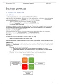
The length of wire between the clips is L. box
Values of R are determined for different values of L.
Figure 5 shows these data.
Figure 5
0 1
. 5 Determine the resistance per metre of X.
[2 marks]
resistance per metre = Ω m−1
IB/M/Jun24/7408/3A
, 7
Do not write
outside the
0 1 . 6 box
Table 1 shows the resistance per metre of various metal wires.
The diameter of X is one of the values of d shown in Table 1.
Table 1
Resistance per metre of wire / Ω m−1
d / mm copper tungsten alumel nichrome
0.38 0.151 0.504 3.15 9.73
0.93 0.0247 0.0824 0.515 1.59
1.63 0.00805 0.0268 0.168 0.518
2.08 0.00494 0.0165 0.103 0.318
3.66 0.00160 0.00532 0.0333 0.103
Identify the metal used for X.
Go on to determine the resistivity of the metal.
State an appropriate SI unit for your answer.
[4 marks]
metal used for X =
resistivity = SI unit =
Question 1 continues on the next page
Turn over ►
IB/M/Jun24/7408/3A
, 8
Do not write
outside the
0 1 . 7 A student adds error bars for R and L to each point on Figure 5. box
She estimates that
each value of R has a percentage uncertainty of 6%
each value of L has an absolute uncertainty of 5 mm.
Compare her error bars for the point at L = 209 mm with her error bars for the point
at L = 388 mm.
[2 marks]
IB/M/Jun24/7408/3A
Paper 3 Section A
(Merged Question Paper and Marking Scheme)
Monday 17 June 2024
Please write clearly in block capitals.
Centre number Candidate number
Surname
Forename(s)
Candidate signat ure
I declare this is my own work.
A-level
PHYSICS
Paper 3
Section A
Monday 17 June 2024 Morning Time allowed: The total time for
Materials
both sections of this paper is
For this paper you must have: 2 hours. You are advised to
a pencil and a ruler spend approximately
a scientific calculator
a Data and Formulae Booklet 70 minutes on this section.
a protractor.
For Examiner’s Use
Instructions
Question Mark
Use black ink or black ball-point pen.
Fill in the boxes at the top of this page. 1
Answer all questions. 2
You must answer the questions in the spaces provided. Do not write 3
outside the box around each page or on blank pages.
If you need extra space for your answer(s), use the lined pages at the end of TOTAL
this book. Write the question number against your answer(s). IB/M/Jun24/G4005/E9
Do all rough work in this book. Cross through any work you do not want
to be marked.
Show all your working.
Information
The marks for questions are shown in brackets.
The maximum mark for this paper is 45.
You are expected to use a scientific calculator where appropriate.
A Data and Formulae Booklet is provided as a loose insert.
,A-Level Physics: Paper 3 Section A: Exam Preview sections
This paper focuses on practical applications and investigations related to the
physics topics you have studied. Section A typically tests your ability to design
experiments, analyze data, and apply theoretical knowledge in practical
contexts.
7408/3A
1. Practical Skills and Investigations:
Experimental Design: You may be asked to design an experiment to
investigate a specific physical principle (e.g., measuring the acceleration
due to gravity, investigating Ohm's Law, or determining the Young's
modulus of a material).
o Key components to consider: variables (independent,
dependent, controlled), methods, safety, and equipment.
Data Analysis: Be prepared to interpret experimental data. This could
involve using graphical methods (e.g., plotting graphs, finding gradients,
and interpreting intercepts) and mathematical methods (e.g., calculating
uncertainty, error propagation, and using appropriate formulae).
Uncertainty and Error: You’ll need to calculate uncertainties in
measurements, including absolute and percentage uncertainty, and
explain how to minimize errors in experiments. Understand how to
report uncertainties when presenting results.
Practical Applications: You could be asked about the practical use of
physical principles in real-world situations (e.g., how materials with
different elastic properties are used in engineering or how radioactivity is
measured in a medical context).
2. Key Topics for Practical Investigation:
Mechanics:
o Investigating motion using different methods (e.g., measuring
velocity, acceleration, or forces in various setups).
o Understanding force and momentum through experiments with
colliding objects or measuring forces in systems like pulleys or
springs.
Electricity:
o Setting up circuits to investigate Ohm’s Law, the relationship
between voltage, current, and resistance in components
(resistors, thermistors, diodes, etc.).
o Experimenting with Kirchhoff’s laws to analyze complex
circuits.
Waves:
o Investigating wave properties such as wavelength, frequency,
and velocity using apparatus like a ripple tank or oscilloscopes.
o Experiments to demonstrate interference and diffraction,
especially for light and sound waves.
Materials:
o Testing the elastic properties of materials, including how to
determine the Young’s modulus of a material through stretching
experiments.
o Investigating the stress-strain relationship and applying it to real
materials like rubber or metal wires.
, 2
Do not write
outside the
Section A box
Answer all questions in this section.
0 1 This question is based on a method to determine the resistivity of a wire (required
practical activity 5).
Figure 1 shows a micrometer screw gauge.
Figure 1
Figure 2 shows an enlarged view of the scales.
Figure 2
IB/M/Jun24/7408/3A
, 3
Do not write
outside the
0 1 . 1 State, in mm, the resolution of the main scale. box
[1 mark]
resolution = mm
0 1 . 2 What is the reading on the micrometer?
Tick (🗸) one box.
[1 mark]
6.22 mm
6.72 mm
6.78 mm
8.22 mm
0 1
. 3 A wire X is placed in the gap between the anvil and the spindle.
State and explain how this gap is closed just before taking a reading of the diameter
of X.
[1 mark]
Question 1 continues on the next page
Turn over ►
IB/M/Jun24/7408/3A
, 4
Do not write
outside the
box
Figure 3 shows a circuit used to determine the resistance per metre of wire X.
Figure 3
Two terminals are used to mount X on a ruler.
Clips are used to connect a voltmeter across the 1.2 Ω resistor.
When the switch is closed, the voltmeter reading is 931 mV.
The switch is then opened and the voltmeter is connected to X as shown in Figure 4.
Figure 4
IB/M/Jun24/7408/3A
, 5
Do not write
outside the
0 1 . 4 When the switch is closed, the voltmeter reading is 397 mV. box
Show that, for the arrangement in Figure 4, the resistance R of the wire between the
clips is about 0.5 Ω.
[2 marks]
Question 1 continues on the next page
Turn over ►
IB/M/Jun24/7408/3A
, 6
Do not write
outside the
The length of wire between the clips is L. box
Values of R are determined for different values of L.
Figure 5 shows these data.
Figure 5
0 1
. 5 Determine the resistance per metre of X.
[2 marks]
resistance per metre = Ω m−1
IB/M/Jun24/7408/3A
, 7
Do not write
outside the
0 1 . 6 box
Table 1 shows the resistance per metre of various metal wires.
The diameter of X is one of the values of d shown in Table 1.
Table 1
Resistance per metre of wire / Ω m−1
d / mm copper tungsten alumel nichrome
0.38 0.151 0.504 3.15 9.73
0.93 0.0247 0.0824 0.515 1.59
1.63 0.00805 0.0268 0.168 0.518
2.08 0.00494 0.0165 0.103 0.318
3.66 0.00160 0.00532 0.0333 0.103
Identify the metal used for X.
Go on to determine the resistivity of the metal.
State an appropriate SI unit for your answer.
[4 marks]
metal used for X =
resistivity = SI unit =
Question 1 continues on the next page
Turn over ►
IB/M/Jun24/7408/3A
, 8
Do not write
outside the
0 1 . 7 A student adds error bars for R and L to each point on Figure 5. box
She estimates that
each value of R has a percentage uncertainty of 6%
each value of L has an absolute uncertainty of 5 mm.
Compare her error bars for the point at L = 209 mm with her error bars for the point
at L = 388 mm.
[2 marks]
IB/M/Jun24/7408/3A