HANDOUTS
COMPUTER 2210- GCE OLEVELS
INPUT AND OUTPUT DEVICES
Input devices
Definition
“Input devices are those devices that provide data or instructions to the CPU from the user.
Functions
An output device usually performs following functions.
i) Receive the data/ instructions from the user in human readable form.
ii) Convert the data/ instruction in binary form.
iii) Sends the data/ instruction to the CPU for processing.
Examples
- Keyboard - Mouse - Joystick etc.
5.1.1 Scanners
Definition
“Scanner is an input device which is use to convert a hard copy into digital file that can be
stored in a computer’s memory.”
Types of Scanner
SCANNERS are either two-dimensional (2D) or three-dimensional (3D).
a) Two-dimensional scanners
Definition
“Two – dimensional scanner is an input device that is used to convert hard copy into digital
file.”
Scanning Process
A number of stages occur when scanning a document:
i) The cover is raised and the document is placed on glass panel and the cover is closed.
ii) A bright light then light up the document.
iii) A scan head moves across the entire document.
iv) An image of the document is produced which is then sent to a lens.
v) The lens focuses the image.
vi) The focused image now falls onto a charged couple device (CCD).
vii) CCD converts each element into electric charge.
viii) These charges are combined to create electronic image.
ix) Software produces a digital image from the electronic form.
Optical Character Recognition
OPTICAL CHARACTER RECOGNITION (OCR) software converts the scanned text
from the document into a TEXT FILE FORMAT. This means the scanned image can now
be edited and manipulated by importing it into a word processor.
Application of 2D scanners at an airport
i) Using OCR Software
2D scanners are used at airports to read passports.
OCR technology produces digital images which represent the passport pages.
OCR software selects the text part and then automatically put the text into the correct fields
of an existing database.
It is possible for the text to be stored in ASCII format.
ii) Using Face Recognition
At many airports the two-dimensional photograph in the passport is also scanned and stored
as a jpeg image.
The passenger’s face is also photographed using a digital camera.
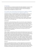
The two digital images are compared using face recognition/detection software.
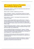
, Figure 1: Face Recognition
Each position is checked when the software tries to compare two facial images. Data
such as:
➢ Distance between the eyes
➢ Width of the nose
➢ Shape of the cheek bones
➢ Length of the jaw line
➢ Shape of the eyebrows is all used to identify a given face.
When the image from the passport and the image taken by the camera are
compared, these key positions on the face determine whether or not the two images
represent the same face.
b) Three-dimensional scanners
Definition
“3D scanners scan solid objects and produce a three-dimensional image.”
Scanning Process
Since solid objects have x, y and z coordinates, these scanners take images at several
points along these three coordinates and join these images to create a digital image of the
solid object.
Uses/ Applications
The scanned images can be used in COMPUTER AIDED DESIGN (CAD) or, more
recently, sent to a 3D printer to produce a working model of the scanned image.
Technologies
Some of the technologies used in 3D scanners are:
- Lasers - Magnetic resonance - White
light.
Application of 3D scanning – computed Tomographic (CT) scanners
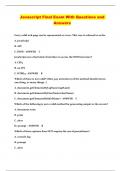
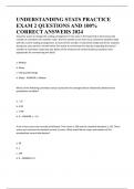
COMPUTED TOMOGRAPHIC (CT) SCANNERS are used to create a 3D image of
a solid object. This is based on TOMOGRAPHY technology. It builds up an image of the
solid object through a series of very thin ‘slices’. Together these 2D ‘slices’ make up a
representation of the 3D solid object.
Each slice is built up by use of X-rays, radio frequencies or gamma imaging. Each
‘slice’ is then stored as a digital image in the computer memory. The whole of the solid
object is represented digitally
Depending on how the image is formed, the type of tomographic scanner can have
different names. For example:
• X – Rays CT Scanners (Computerized Tomography
• Radio Frequencies MRI (Magnetic Resonance Imaging
• Gamma Rays SPECT (Single Photon Emission Computed Tomography)
, Figure 2: Computerized Tomography
5.1.2 Barcode Readers/ Barcode Scanners
a) Barcode
“A barcode is a series of dark and light parallel lines of varying thickness. The
numbers 0 to 9 are each represented by a unique series of lines.”
Universal Product Code – Version A
• UPC - Version A adopts different codes for digits appearing on the left and for digits
appearing on the right.
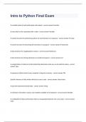
• The actual left-hand and right-hand sides of the barcode are separated using guard bars.
• The structure of these guard bars is shown in Figure 3.
• Figure 4 is an example of a barcode showing the left-hand side and right-hand side and the
three sets of guard bars.
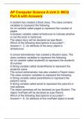
• Each digit is represented by bars of 1 to 4 blocks thick as shown in Figure 5.
Figure 3: Guard Bar’s Structure Figure 4: Use of Guard Bar
Figure 5: Bar Codes
COMPUTER 2210- GCE OLEVELS
INPUT AND OUTPUT DEVICES
Input devices
Definition
“Input devices are those devices that provide data or instructions to the CPU from the user.
Functions
An output device usually performs following functions.
i) Receive the data/ instructions from the user in human readable form.
ii) Convert the data/ instruction in binary form.
iii) Sends the data/ instruction to the CPU for processing.
Examples
- Keyboard - Mouse - Joystick etc.
5.1.1 Scanners
Definition
“Scanner is an input device which is use to convert a hard copy into digital file that can be
stored in a computer’s memory.”
Types of Scanner
SCANNERS are either two-dimensional (2D) or three-dimensional (3D).
a) Two-dimensional scanners
Definition
“Two – dimensional scanner is an input device that is used to convert hard copy into digital
file.”
Scanning Process
A number of stages occur when scanning a document:
i) The cover is raised and the document is placed on glass panel and the cover is closed.
ii) A bright light then light up the document.
iii) A scan head moves across the entire document.
iv) An image of the document is produced which is then sent to a lens.
v) The lens focuses the image.
vi) The focused image now falls onto a charged couple device (CCD).
vii) CCD converts each element into electric charge.
viii) These charges are combined to create electronic image.
ix) Software produces a digital image from the electronic form.
Optical Character Recognition
OPTICAL CHARACTER RECOGNITION (OCR) software converts the scanned text
from the document into a TEXT FILE FORMAT. This means the scanned image can now
be edited and manipulated by importing it into a word processor.
Application of 2D scanners at an airport
i) Using OCR Software
2D scanners are used at airports to read passports.
OCR technology produces digital images which represent the passport pages.
OCR software selects the text part and then automatically put the text into the correct fields
of an existing database.
It is possible for the text to be stored in ASCII format.
ii) Using Face Recognition
At many airports the two-dimensional photograph in the passport is also scanned and stored
as a jpeg image.
The passenger’s face is also photographed using a digital camera.
The two digital images are compared using face recognition/detection software.
, Figure 1: Face Recognition
Each position is checked when the software tries to compare two facial images. Data
such as:
➢ Distance between the eyes
➢ Width of the nose
➢ Shape of the cheek bones
➢ Length of the jaw line
➢ Shape of the eyebrows is all used to identify a given face.
When the image from the passport and the image taken by the camera are
compared, these key positions on the face determine whether or not the two images
represent the same face.
b) Three-dimensional scanners
Definition
“3D scanners scan solid objects and produce a three-dimensional image.”
Scanning Process
Since solid objects have x, y and z coordinates, these scanners take images at several
points along these three coordinates and join these images to create a digital image of the
solid object.
Uses/ Applications
The scanned images can be used in COMPUTER AIDED DESIGN (CAD) or, more
recently, sent to a 3D printer to produce a working model of the scanned image.
Technologies
Some of the technologies used in 3D scanners are:
- Lasers - Magnetic resonance - White
light.
Application of 3D scanning – computed Tomographic (CT) scanners
COMPUTED TOMOGRAPHIC (CT) SCANNERS are used to create a 3D image of
a solid object. This is based on TOMOGRAPHY technology. It builds up an image of the
solid object through a series of very thin ‘slices’. Together these 2D ‘slices’ make up a
representation of the 3D solid object.
Each slice is built up by use of X-rays, radio frequencies or gamma imaging. Each
‘slice’ is then stored as a digital image in the computer memory. The whole of the solid
object is represented digitally
Depending on how the image is formed, the type of tomographic scanner can have
different names. For example:
• X – Rays CT Scanners (Computerized Tomography
• Radio Frequencies MRI (Magnetic Resonance Imaging
• Gamma Rays SPECT (Single Photon Emission Computed Tomography)
, Figure 2: Computerized Tomography
5.1.2 Barcode Readers/ Barcode Scanners
a) Barcode
“A barcode is a series of dark and light parallel lines of varying thickness. The
numbers 0 to 9 are each represented by a unique series of lines.”
Universal Product Code – Version A
• UPC - Version A adopts different codes for digits appearing on the left and for digits
appearing on the right.
• The actual left-hand and right-hand sides of the barcode are separated using guard bars.
• The structure of these guard bars is shown in Figure 3.
• Figure 4 is an example of a barcode showing the left-hand side and right-hand side and the
three sets of guard bars.
• Each digit is represented by bars of 1 to 4 blocks thick as shown in Figure 5.
Figure 3: Guard Bar’s Structure Figure 4: Use of Guard Bar
Figure 5: Bar Codes